
User's Manual
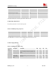
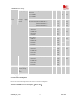
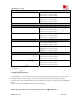


Table Of Contents
- Contents
- Version history
- 1 Introduction
- 2 SIM900B Overview
- 3 Application Interface
- 3.1 SIM900B Pin Description
- 3.2 Operating Modes
- 3.3 Power Supply
- 3.4 Power Up and Power Down Scenarios
- 3.5 Power Saving
- 3.6 Summary of State Transitions (except SLEEP mode)
- 3.7 RTC Backup
- 3.8 Serial Interfaces
- 3.9 Audio Interfaces
- 3.10 Buzzer
- 3.11 SIM Card Interface
- 3.12 LCD Display Interface
- 3.13 Keypad Interface
- 3.14 ADC
- 3.15 Behaviors of the RI
- 3.16 Network Status Indication
- 3.17 General Purpose Input Output (GPIO)
- 4 Antenna Interface
- 5 Electrical, Reliability and Radio Characteristics
- 6 Mechanics

SIM900B Hardware Design
Table 25: Absolute maximum ratings
Parameter Min Max Unit
VBAT - 5.5 V
Peak current of power supply 0 3.0 A
Voltage at digit pins* -0.3 3.1 V
I
I
* - 10 mA
I
O
* - 10 mA
*For digital interface pins, such as keypad, GPIO, UART and LCD.
5.2 Operating Temperatures
The operating temperature is listed in following table:
Table
26: SIM900B operating temperature
Parameter Min Typ Max Unit
Ambient temperature -30 +25 +80 ℃
Restricted operation* -40 to -30 +80 to +85 ℃
Storage temperature -45 +90 ℃
* The SIM900B does work, but deviations from the GSM specification may occur.
5.3 Power Supply Ratings
Table 27: SIM900B power supply ratings
Parameter Description Conditions Min Typ Max Unit
Supply voltage Voltage must stay within the min/max
values, including voltage drop, ripple, and
spikes.
3.1 4.0 4.8 V VBAT
Voltage drop
during transmit
burst
Normal condition, power control level for
Pout max
300 mV
SIM900B_HD_V1.03 24.06.2010
51