
User's Manual

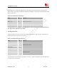

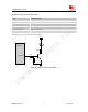
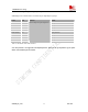

Table Of Contents
- Contents
- Version history
- 1 Introduction
- 2 SIM900B Overview
- 3 Application Interface
- 3.1 SIM900B Pin Description
- 3.2 Operating Modes
- 3.3 Power Supply
- 3.4 Power Up and Power Down Scenarios
- 3.5 Power Saving
- 3.6 Summary of State Transitions (except SLEEP mode)
- 3.7 RTC Backup
- 3.8 Serial Interfaces
- 3.9 Audio Interfaces
- 3.10 Buzzer
- 3.11 SIM Card Interface
- 3.12 LCD Display Interface
- 3.13 Keypad Interface
- 3.14 ADC
- 3.15 Behaviors of the RI
- 3.16 Network Status Indication
- 3.17 General Purpose Input Output (GPIO)
- 4 Antenna Interface
- 5 Electrical, Reliability and Radio Characteristics
- 6 Mechanics

SIM900B Hardware Design
4.1 Module RF Output Power
Table 22: SIM900B conducted RF output power
Frequency Max Min
GSM850 33dBm ±2db 5dBm±5db
EGSM900 33dBm ±2db 5dBm±5db
DCS1800 30dBm ±2db 0dBm±5db
PCS1900 30dBm ±2db 0dBm±5db
4.2 Module RF Receive Sensitivity
Table 23: SIM900B conducted RF receive sensitivity
Frequency
Receive sensitivity(Typical)
Receive sensitivity(Max)
GSM850 -109dBm -107dBm
EGSM900 -109dBm -107dBm
DCS1800 -109dBm -107dBm
PCS1900 -109dBm -107dBm
4.3 Module Operating Frequencies
Table 24: SIM900B operating frequencies
Frequency Receive Transmit
GSM850 869 ~ 894MHz 824 ~ 849 MHz
EGSM900 925 ~ 960MHz 880 ~ 915MHz
DCS1800 1805 ~ 1880MHz 1710 ~ 1785MHz
PCS1900 1930 ~ 1990MHz 1850 ~ 1910MHz
5 Electrical, Reliability and Radio Characteristics
5.1 Absolute Maximum Ratings
The absolute maximum ratings stated in Table 28 are stress ratings under non-operating conditions. Stresses
beyond any of these limits will cause permanent damage to SIM900B.
SIM900B_HD_V1.03 24.06.2010
50