
User's Manual

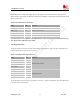

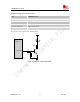
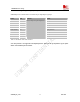

Table Of Contents
- Contents
- Version history
- 1 Introduction
- 2 SIM900B Overview
- 3 Application Interface
- 3.1 SIM900B Pin Description
- 3.2 Operating Modes
- 3.3 Power Supply
- 3.4 Power Up and Power Down Scenarios
- 3.5 Power Saving
- 3.6 Summary of State Transitions (except SLEEP mode)
- 3.7 RTC Backup
- 3.8 Serial Interfaces
- 3.9 Audio Interfaces
- 3.10 Buzzer
- 3.11 SIM Card Interface
- 3.12 LCD Display Interface
- 3.13 Keypad Interface
- 3.14 ADC
- 3.15 Behaviors of the RI
- 3.16 Network Status Indication
- 3.17 General Purpose Input Output (GPIO)
- 4 Antenna Interface
- 5 Electrical, Reliability and Radio Characteristics
- 6 Mechanics

SIM900B Hardware Design
3.17 General Purpose Input Output (GPIO)
SIM900B provides a limited number of General Purpose Input/Output signal pin.
Name Pin Function RESET
GPIO0 32 Input pull down
GPIO1/KBC4 35 Input pull down
GPIO2/KBC3 33 Input pull down
GPIO3/KBC2 31 Input pull down
GPIO4/KBC1 29 Input pull down
GPIO6/KBR4 45 Input pull down
GPIO7/KBR3 43 Input pull down
GPIO8/KBR2 41 Input pull down
GPIO9/KBR1 39
General Purpose Input/Output Port
Input pull down
Table
21: Pin define of the GPIO interface
Note: This function is not supported in the default firmware. There must be special firmware if you require.
Please contact SIMCom for more details .
SIM900B_HD_V1.03 24.06.2010
48