
User's Manual

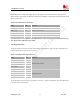
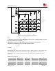

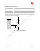
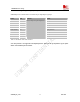

Table Of Contents
- Contents
- Version history
- 1 Introduction
- 2 SIM900B Overview
- 3 Application Interface
- 3.1 SIM900B Pin Description
- 3.2 Operating Modes
- 3.3 Power Supply
- 3.4 Power Up and Power Down Scenarios
- 3.5 Power Saving
- 3.6 Summary of State Transitions (except SLEEP mode)
- 3.7 RTC Backup
- 3.8 Serial Interfaces
- 3.9 Audio Interfaces
- 3.10 Buzzer
- 3.11 SIM Card Interface
- 3.12 LCD Display Interface
- 3.13 Keypad Interface
- 3.14 ADC
- 3.15 Behaviors of the RI
- 3.16 Network Status Indication
- 3.17 General Purpose Input Output (GPIO)
- 4 Antenna Interface
- 5 Electrical, Reliability and Radio Characteristics
- 6 Mechanics

SIM900B Hardware Design
3.12 LCD Display Interface
SIM900B provides a serial LCD display interface that supports serial communication with LCD device.
When used as LCD interface, the following table is the pin definition. LCD interface timing should be united
with the LCD device.
Table 16: Pin define of the LCD interface
Name Pin Function
DISP_DATA 18 Display data output
DISP_CLK 20 Display clock for LCD
DISP_CS 22 Display enable
DISP_D/C 24 Display data or command select
DISP_RST 26 LCD reset
Note: This function is not supported in the default firmware. There must be some customized firmware if you
want. Please contact SIMCom for more details.
3.13 Keypad Interface
The keypad interface consists of 5 keypad column outputs and 4 keypad row inputs. The basic configuration is 5
keypad columns and 4 keypad rows, giving 20 keys.
Table
17: Pin define of the keypad interface
Name Pin Function
KBC0 27
GPIO4/KBC1 29
GPIO3/KBC2 31
GPIO2/KBC3 33
GPIO1/KBC4 35
Keypad matrix column
GPIO9/KBR1 39
GPIO8/KBR2 41
GPIO7/KBR3 43
GPIO6/KBR4 45
Keypad matrix row
The keypad interface allows a direct external matrix connection. A typical recommended circuit about the keypad
is as shown in the following figure.
SIM900B_HD_V1.03 24.06.2010
44