
User's Manual

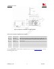
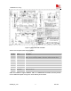
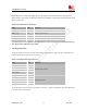

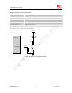
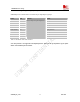
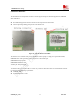

Table Of Contents
- Contents
- Version history
- 1 Introduction
- 2 SIM900B Overview
- 3 Application Interface
- 3.1 SIM900B Pin Description
- 3.2 Operating Modes
- 3.3 Power Supply
- 3.4 Power Up and Power Down Scenarios
- 3.5 Power Saving
- 3.6 Summary of State Transitions (except SLEEP mode)
- 3.7 RTC Backup
- 3.8 Serial Interfaces
- 3.9 Audio Interfaces
- 3.10 Buzzer
- 3.11 SIM Card Interface
- 3.12 LCD Display Interface
- 3.13 Keypad Interface
- 3.14 ADC
- 3.15 Behaviors of the RI
- 3.16 Network Status Indication
- 3.17 General Purpose Input Output (GPIO)
- 4 Antenna Interface
- 5 Electrical, Reliability and Radio Characteristics
- 6 Mechanics

SIM900B Hardware Design
SIM900B_HD_V1.03 24.06.2010
43
Figure 27: Molex 91228 SIM card holder
Table
15: Pin description (Molex SIM card holder)
Pin Name Signal Description
C1
SIM_VDD SIM Card Power supply, it can identify automatically the SIM Card power
mode,one is 3.0V±10%, another is 1.8V±10%. Current is about 10mA.
C2
SIM_RST SIM Card Reset
C3
SIM_CLK SIM Card Clock
C4
GND Connect to GND
C5
GND Connect to GND
C6
VPP Not connect
C7
SIM_DATA SIM Card data I/O
C8
SIM_PRESENCE Detect SIM Card Presence
NOTE: the sim900B can support embedded SIM IC or embedded SIM card holder, but these functions
aren’t included in the default version, please contact SIMCom for more details.