
User's Manual

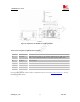
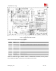

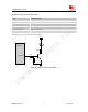
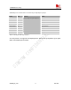

Table Of Contents
- Contents
- Version history
- 1 Introduction
- 2 SIM900B Overview
- 3 Application Interface
- 3.1 SIM900B Pin Description
- 3.2 Operating Modes
- 3.3 Power Supply
- 3.4 Power Up and Power Down Scenarios
- 3.5 Power Saving
- 3.6 Summary of State Transitions (except SLEEP mode)
- 3.7 RTC Backup
- 3.8 Serial Interfaces
- 3.9 Audio Interfaces
- 3.10 Buzzer
- 3.11 SIM Card Interface
- 3.12 LCD Display Interface
- 3.13 Keypad Interface
- 3.14 ADC
- 3.15 Behaviors of the RI
- 3.16 Network Status Indication
- 3.17 General Purpose Input Output (GPIO)
- 4 Antenna Interface
- 5 Electrical, Reliability and Radio Characteristics
- 6 Mechanics

SIM900B Hardware Design
MODULE
SMF05C
SIM_VDD
SIM_CLK
SIM_DATA
SIM_RST
SIM_PRESENCE
VCC GND
RST VPP
CLK I/O
PRESENCE GND
22R
22R
22R
220nF
MOLEX-91228
SIM
CARD
22pF
Figure 24: Reference circuit of the 8 pins SIM card
If the SIM card detection function don’t use, the SIM_PRESENCE pin can be keep open. The reference circuit
about 6 pins SIM card illustrates as following figure.
MODULE
SMF05C
SIM_VDD
SIM_CLK
SIM_DATA
SIM_RST
22pF
VCC GND
RST VPP
CLK I/O
22R
22R
22R
220nF
C707 10M006 512 2
SIM
CARD
Figure 25: Reference circuit of the 6 pins SIM card
3.11.2 Design Considerations for SIM Card Holder
For 6 pins SIM card holder, we recommend to use Amphenol C707 10M006 512 2, the user can visit
http://www.amphenol.com
for more information about the holder.
SIM900B_HD_V1.03 24.06.2010
41