
User's Manual

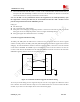


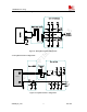

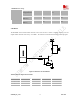
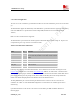
Table Of Contents
- Contents
- Version history
- 1 Introduction
- 2 SIM900B Overview
- 3 Application Interface
- 3.1 SIM900B Pin Description
- 3.2 Operating Modes
- 3.3 Power Supply
- 3.4 Power Up and Power Down Scenarios
- 3.5 Power Saving
- 3.6 Summary of State Transitions (except SLEEP mode)
- 3.7 RTC Backup
- 3.8 Serial Interfaces
- 3.9 Audio Interfaces
- 3.10 Buzzer
- 3.11 SIM Card Interface
- 3.12 LCD Display Interface
- 3.13 Keypad Interface
- 3.14 ADC
- 3.15 Behaviors of the RI
- 3.16 Network Status Indication
- 3.17 General Purpose Input Output (GPIO)
- 4 Antenna Interface
- 5 Electrical, Reliability and Radio Characteristics
- 6 Mechanics

SIM900B Hardware Design
3.11 SIM Card Interface
3.11.1 SIM Card Application
The user can use AT Command to get information in SIM card. For more information, please refer to document
[1].
The SIM interface supports the functionality of the GSM Phase 1 specification and also supports the functionality
of the new GSM Phase 2+ specification for FAST 64 kbps SIM (intended for use with a SIM application
Tool-kit).
Both 1.8V and 3.0V SIM Cards are supported.
The SIM interface is powered from an internal regulator in the module having normal voltage 3V. All pins reset
as outputs driving low. Logic levels are as described in table
Table
13: Pin define of the SIM interface
Name Pin Function
SIM_VDD 19 SIM Card Power output automatic output on SIM mode,
one is 3.0V±10%, another is 1.8V±10%. Current is about
10mA.
SIM_DATA 21 SIM Card data I/O
SIM_CLK 23 SIM Card Clock
SIM_RST 25 SIM Card Reset
SIM_PRESENCE 16 SIM Card Presence
Following is the reference circuit about SIM interface. We recommend an Electro-Static discharge device ST
(www.st.com
) ESDA6V1W5 or ON SEMI (www.onsemi.com ) SMF05C for “ESD ANTI”. The 22Ω resistors
showed in the following figure should be added in series on the IO line between the module and the SIM card for
protecting the SIM I/O port. The pull up resistor (about 15KΩ) on the SIM_DATA line already added in the
module. Note that the SIM peripheral circuit should be close to the SIM card socket.
The SIM_PRESENCE pin is used for detecting the SIM card insert or removal. The user can use the AT
command “AT+CSDT” to set the SIMCARD configuration. For detail of this AT command, please refer to
document [1]:
8 pins SIM card holder can be selected . The reference circuit about 8 pins SIM card holder illustrates as
following figure.
SIM900B_HD_V1.03 24.06.2010
40