
User's Manual
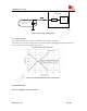

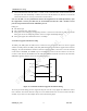


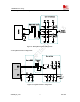

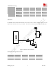
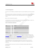
Table Of Contents
- Contents
- Version history
- 1 Introduction
- 2 SIM900B Overview
- 3 Application Interface
- 3.1 SIM900B Pin Description
- 3.2 Operating Modes
- 3.3 Power Supply
- 3.4 Power Up and Power Down Scenarios
- 3.5 Power Saving
- 3.6 Summary of State Transitions (except SLEEP mode)
- 3.7 RTC Backup
- 3.8 Serial Interfaces
- 3.9 Audio Interfaces
- 3.10 Buzzer
- 3.11 SIM Card Interface
- 3.12 LCD Display Interface
- 3.13 Keypad Interface
- 3.14 ADC
- 3.15 Behaviors of the RI
- 3.16 Network Status Indication
- 3.17 General Purpose Input Output (GPIO)
- 4 Antenna Interface
- 5 Electrical, Reliability and Radio Characteristics
- 6 Mechanics

SIM900B Hardware Design
Output swing
Voltage(differentia
l)
2.2 V
RL=32 Ohm
THD=0.1%
- 91 - mW
RL=32 Ohm
THD=1%
- 96 - mW
3.10 Buzzer
The BUZZER on the board-to-board connector can be used to drive a buzzer to indicate incoming call. The
output volume of buzzer can be set by “AT+CRSL”. The reference circuit for buzzer shown as following figure:
MODULE
4.7K
47K
VBAT
BUZZER
Figure 23: Reference circuit of Buzzer
Table
12: Buzzer Output Characteristics
Parameter Min Typ Max Unit
Working Voltage 2.4 2.85 3.0 V
Working Current 2 mA
Load Resistance 1 k Ohms
SIM900B_HD_V1.03 24.06.2010
39