
User's Manual
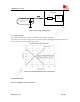

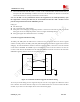


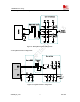

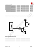
Table Of Contents
- Contents
- Version history
- 1 Introduction
- 2 SIM900B Overview
- 3 Application Interface
- 3.1 SIM900B Pin Description
- 3.2 Operating Modes
- 3.3 Power Supply
- 3.4 Power Up and Power Down Scenarios
- 3.5 Power Saving
- 3.6 Summary of State Transitions (except SLEEP mode)
- 3.7 RTC Backup
- 3.8 Serial Interfaces
- 3.9 Audio Interfaces
- 3.10 Buzzer
- 3.11 SIM Card Interface
- 3.12 LCD Display Interface
- 3.13 Keypad Interface
- 3.14 ADC
- 3.15 Behaviors of the RI
- 3.16 Network Status Indication
- 3.17 General Purpose Input Output (GPIO)
- 4 Antenna Interface
- 5 Electrical, Reliability and Radio Characteristics
- 6 Mechanics

SIM900B Hardware Design
3.9.2 Microphone Interfaces Configuration
10pF
33pF
33pF
33pF
Close to Microphone
MICxP
MICxN
GND
GND
Differential layout
AGND
MODULE
Electret
Microphone
GND
GND
10pF
10pF
GND
GND
ESD
ANTI
ESD
ANTI
AGND
Figure 21: Microphone interface configuration
3.9.3 Earphone Interface Configuration
1
2
4
3
Amphenol
SPK2P
MIC2N
MIC2P
1uF
10R
100R
33pF
GND
GNDGND
GND
Close to MODULE
Close to Socket
Differential
layout
33pF 33pF
33pF
33pF 10pF
GND
GND
GND
GND
MODULE
GND
GND
SPK2N
GND
Figure 22: Earphone interface configuration
SIM900B_HD_V1.03 24.06.2010
37