
User's Manual
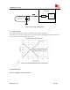

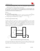


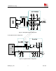

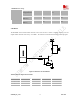
Table Of Contents
- Contents
- Version history
- 1 Introduction
- 2 SIM900B Overview
- 3 Application Interface
- 3.1 SIM900B Pin Description
- 3.2 Operating Modes
- 3.3 Power Supply
- 3.4 Power Up and Power Down Scenarios
- 3.5 Power Saving
- 3.6 Summary of State Transitions (except SLEEP mode)
- 3.7 RTC Backup
- 3.8 Serial Interfaces
- 3.9 Audio Interfaces
- 3.10 Buzzer
- 3.11 SIM Card Interface
- 3.12 LCD Display Interface
- 3.13 Keypad Interface
- 3.14 ADC
- 3.15 Behaviors of the RI
- 3.16 Network Status Indication
- 3.17 General Purpose Input Output (GPIO)
- 4 Antenna Interface
- 5 Electrical, Reliability and Radio Characteristics
- 6 Mechanics

SIM900B Hardware Design
used to set the side-tone level. In addition, “AT+CLVL” can be used to adjust the output gain level of both
receiver and speaker at the same time, use AT+CHFA to activate one of the two audio channels and deactivate the
other one.. For more details, please refer to document [1].
Note: Use AT command AT+CHFA to select_audio channel:
0— AIN1/AOUT1 (normal audio channel), the default value is 0.
1— AIN2/AOUT2(aux_audio channel) .
It is suggested that you adopt one of the following two matching circuits in order to improve audio performance.
The difference audio signals have to be layout according to difference signal layout rules. As show in following
figures (Note: all components package are 0603.) If an amplifier circuit for audio is needed, then National
company’s LM4890 is recommended. Of course it can select it according to your requirement.
3.9.1 Speaker Interface Configuration
Figure 19: Speaker interface configuration
Figure 20: Speaker interface with amplifier configuration
SIM900B_HD_V1.03 24.06.2010
36