
User's Manual


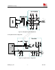

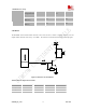
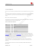
Table Of Contents
- Contents
- Version history
- 1 Introduction
- 2 SIM900B Overview
- 3 Application Interface
- 3.1 SIM900B Pin Description
- 3.2 Operating Modes
- 3.3 Power Supply
- 3.4 Power Up and Power Down Scenarios
- 3.5 Power Saving
- 3.6 Summary of State Transitions (except SLEEP mode)
- 3.7 RTC Backup
- 3.8 Serial Interfaces
- 3.9 Audio Interfaces
- 3.10 Buzzer
- 3.11 SIM Card Interface
- 3.12 LCD Display Interface
- 3.13 Keypad Interface
- 3.14 ADC
- 3.15 Behaviors of the RI
- 3.16 Network Status Indication
- 3.17 General Purpose Input Output (GPIO)
- 4 Antenna Interface
- 5 Electrical, Reliability and Radio Characteristics
- 6 Mechanics

SIM900B Hardware Design
Figure 18: RS232 level converter circuit
3.9 Audio Interfaces
Table 9: Pin define of the Audio interface
Name Pin Function
MIC1P 53 Microphone1 input +
MIC1N 55 Microphone1 input -
SPK1P 54 Audio1 output+
(AIN1/AOUT1)
SPK1N 56 Audio1 output-
MIC2P 57 Microphone2 input +
MIC2N 59 Microphone2 input -
SPK2P 58 Audio2 output+
(AIN2/AOUT2)
SPK2N 60 Audio2 output-
The module provides two analogy input channels, AIN1 and AIN2, which may be used for both microphone and
line inputs. The electret microphone is recommended when the interface is used for microphone. One of the two
channels is typically used with a microphone built into a handset. The other channel is typically used with an
external microphone or external line input. The module analogy input configuration is determined by control
register settings and established using analogy multiplexes.
For each channels, “AT+CMIC” can be used to adjust the input gain level of microphone, “AT+SIDET” can be
SIM900B_HD_V1.03 24.06.2010
35