
User's Manual
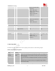
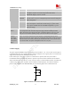
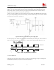
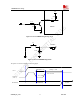
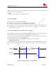


Table Of Contents
- Contents
- Version history
- 1 Introduction
- 2 SIM900B Overview
- 3 Application Interface
- 3.1 SIM900B Pin Description
- 3.2 Operating Modes
- 3.3 Power Supply
- 3.4 Power Up and Power Down Scenarios
- 3.5 Power Saving
- 3.6 Summary of State Transitions (except SLEEP mode)
- 3.7 RTC Backup
- 3.8 Serial Interfaces
- 3.9 Audio Interfaces
- 3.10 Buzzer
- 3.11 SIM Card Interface
- 3.12 LCD Display Interface
- 3.13 Keypad Interface
- 3.14 ADC
- 3.15 Behaviors of the RI
- 3.16 Network Status Indication
- 3.17 General Purpose Input Output (GPIO)
- 4 Antenna Interface
- 5 Electrical, Reliability and Radio Characteristics
- 6 Mechanics

SIM900B Hardware Design
3.7 RTC Backup
The RTC (Real Time Clock) power supply of module can be provided by an external capacitor or a battery
(rechargeable or non-chargeable) through the VRTC.
Note: If the RTC function is enabled, a battery or capacitor should be connected with the VRTC pin. If this
function is not needed, a 4.7uF capacitor is recommended to connect to the VRTC pin.
The following figures show various sample circuits for RTC backup.
RTC
Core
10K
SIM900B
VRTC
Non-chargeable
Backup Battery
Figure 12: RTC supply from non-chargeable battery
RTC
Core
10K
SIM900B
VRTC
Rechargeable
Backup Battery
Figure 13: RTC supply from rechargeable battery
SIM900B_HD_V1.03 24.06.2010
30