
User's Manual
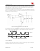
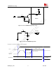
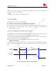


Table Of Contents
- Contents
- Version history
- 1 Introduction
- 2 SIM900B Overview
- 3 Application Interface
- 3.1 SIM900B Pin Description
- 3.2 Operating Modes
- 3.3 Power Supply
- 3.4 Power Up and Power Down Scenarios
- 3.5 Power Saving
- 3.6 Summary of State Transitions (except SLEEP mode)
- 3.7 RTC Backup
- 3.8 Serial Interfaces
- 3.9 Audio Interfaces
- 3.10 Buzzer
- 3.11 SIM Card Interface
- 3.12 LCD Display Interface
- 3.13 Keypad Interface
- 3.14 ADC
- 3.15 Behaviors of the RI
- 3.16 Network Status Indication
- 3.17 General Purpose Input Output (GPIO)
- 4 Antenna Interface
- 5 Electrical, Reliability and Radio Characteristics
- 6 Mechanics

SIM900B Hardware Design
4.7k
47k
Turn on impulse
3V
1K
100K
POWERKEY
Module
Figure 6: Turn on SIM900B using driving circuit
S1
PWRKEY
TVS1
Figure 7: Turn on SIM900B using button
The power on scenarios illustrates as following figure.
V
IL
=1.2V
V
IH
> 2.55V
Pulldown >1s
VBAT
PWRKEY
(INPUT)
Delay > 2.2s
Serial Port
Undefined
Active
SIM900B_HD_V1.03 24.06.2010
25