
User's Manual
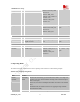
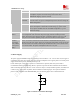
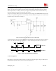
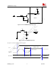
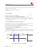


Table Of Contents
- Contents
- Version history
- 1 Introduction
- 2 SIM900B Overview
- 3 Application Interface
- 3.1 SIM900B Pin Description
- 3.2 Operating Modes
- 3.3 Power Supply
- 3.4 Power Up and Power Down Scenarios
- 3.5 Power Saving
- 3.6 Summary of State Transitions (except SLEEP mode)
- 3.7 RTC Backup
- 3.8 Serial Interfaces
- 3.9 Audio Interfaces
- 3.10 Buzzer
- 3.11 SIM Card Interface
- 3.12 LCD Display Interface
- 3.13 Keypad Interface
- 3.14 ADC
- 3.15 Behaviors of the RI
- 3.16 Network Status Indication
- 3.17 General Purpose Input Output (GPIO)
- 4 Antenna Interface
- 5 Electrical, Reliability and Radio Characteristics
- 6 Mechanics

SIM900B Hardware Design
3.3.2 Minimizing Power Losses
When designing the power supply for your application please pay specific attention to power losses. Ensure that
the input voltage VBAT never drops below 3.2V even in a transmit burst where current consumption can rise to
typical peaks of 2A. If the power voltage drops below 3.2V, the module may be switched off. The PCB traces
from the VBAT pins to the power source must be wide enough to decrease voltage drops in the transmitting burst
mode.
3.3.3 Monitoring Power Supply
To monitor the supply voltage, the user can use the “AT+CBC” command which include a parameter: voltage
value (in mV).
The voltage is continuously measured at intervals depending on the operating mode. The displayed voltage (in
mV) is averaged over the last measuring period before the “AT+CBC” command is executed.
For details please refer to document [1]
3.4 Power Up and Power Down Scenarios
In general, be sure not to turn on SIM900B while it is beyond the safety limits of voltage and temperature stated
in Chapter 3.4.2. SIM900B would immediately switch off after having started and detected these inappropriate
conditions. In extreme cases this can cause permanent damage to the module.
3.4.1 Turn on SIM900B
SIM900B can be turned on by the following way, which is described in following chapters:
z Via PWRKEY pin: starts normal operating mode (please refer to chapter 3.4.1.1);
Note: The AT command must be set after the SIM900B is power on and Unsolicited Result Code “RDY” is
received from the serial port. However if the SIM900B is set autobauding, the serial port will receive nothing.
The AT commands can be set after the SIM900B is power on. “AT+IPR=x” can be used to set a fixed baud
rate and save the configuration to non-volatile flash memory. After the configuration is saved as fixed baud
rate, the Code “RDY” should be received from the serial port all the time that the SIM900B is power on.
Please refer to the chapter “AT+IPR” in document [1].
3.4.1.1 Turn on SIM900B Using the PWRKEY Pin (Power on)
The SIM900B can be turn on by driving the PWRKEY to a low level voltage for some time and then release.
This pin has pulled up to a 3V voltage source in the module. The simple circuit illustrates as the following
figures.
SIM900B_HD_V1.03 24.06.2010
24