
User's Manual
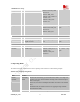
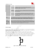
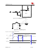
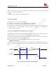

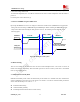

Table Of Contents
- Contents
- Version history
- 1 Introduction
- 2 SIM900B Overview
- 3 Application Interface
- 3.1 SIM900B Pin Description
- 3.2 Operating Modes
- 3.3 Power Supply
- 3.4 Power Up and Power Down Scenarios
- 3.5 Power Saving
- 3.6 Summary of State Transitions (except SLEEP mode)
- 3.7 RTC Backup
- 3.8 Serial Interfaces
- 3.9 Audio Interfaces
- 3.10 Buzzer
- 3.11 SIM Card Interface
- 3.12 LCD Display Interface
- 3.13 Keypad Interface
- 3.14 ADC
- 3.15 Behaviors of the RI
- 3.16 Network Status Indication
- 3.17 General Purpose Input Output (GPIO)
- 4 Antenna Interface
- 5 Electrical, Reliability and Radio Characteristics
- 6 Mechanics

SIM900B Hardware Design
SIM_CLK O SIM clock
SIM_RST O SIM reset
VIHmin=0.85*SIM_VDD
VILmin= 0V
VIHmax= SIM_VDD
VOHmin= SIM_VDD-0.1V
VOLmax=0.1V
VOHmax= SIM_VDD
VOLmin= 0V
SIM_PRESENCE I SIM detect VILmax=0.15 *VDD_EXT
VIHmin=0.85*VDD_EXT
VILmin= 0V
VIHmax= VDD_EXT
If unused keep
open
ADC
PIN NAME I/O DESCRIPTION DC CHARACTERISTICS COMMENT
ADC0 I General purpose analog to
digital converter.
Input voltage range: 0V ~
2.8V
If unused keep
open
Pulse Width Modulation
PIN NAME I/O DESCRIPTION DC CHARACTERISTICS COMMENT
BUZZER O PWM Output VOHmin= VDD_EXT-0.1V
VOLmax=0.1V
VOHmax= VDD_EXT
VOLmin=0
If unused keep
open
3.2 Operating Modes
The table below briefly summarizes the various operating modes referred to in the following chapters.
Table
6: Overview of operating modes
Mode Function
GSM/GPRS
SLEEP
Module will automatically go into SLEEP mode if DTR is set to high level
and there is no on air and no hardware interrupt (such as GPIO interrupt or
data on serial port).
In this case, the current consumption of module will reduce to the minimal
level.
In SLEEP mode, the module can still receive paging message and SMS
from the BTS normally.
Normal
operation
GSM IDLE Software is active. Module has registered to the GSM network, and the
SIM900B_HD_V1.03 24.06.2010
21