
User's Manual

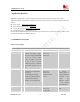
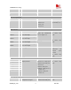
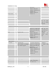
Table Of Contents
- Contents
- Version history
- 1 Introduction
- 2 SIM900B Overview
- 3 Application Interface
- 3.1 SIM900B Pin Description
- 3.2 Operating Modes
- 3.3 Power Supply
- 3.4 Power Up and Power Down Scenarios
- 3.5 Power Saving
- 3.6 Summary of State Transitions (except SLEEP mode)
- 3.7 RTC Backup
- 3.8 Serial Interfaces
- 3.9 Audio Interfaces
- 3.10 Buzzer
- 3.11 SIM Card Interface
- 3.12 LCD Display Interface
- 3.13 Keypad Interface
- 3.14 ADC
- 3.15 Behaviors of the RI
- 3.16 Network Status Indication
- 3.17 General Purpose Input Output (GPIO)
- 4 Antenna Interface
- 5 Electrical, Reliability and Radio Characteristics
- 6 Mechanics

SIM900B Hardware Design
GPIO2/ KBC3 I/O
GPIO3/ KBC2 I/O
GPIO4/ KBC1 I/O
GPIO6/ KBR3 I/O
GPIO7/ KBR4 I/O
GPIO8/ KBR2 I/O
GPIO9/ KBR1 I/O
KBR0 I
KBC0 O
VILmin= 0V
VIHmax= VDD_EXT
VOHmin= VDD_EXT-0.1V
VOLmax=0.1V
VOHmax= VDD_EXT
VOLmin= 0V
Just for power
down, If unused
keep open
Serial port
PIN NAME I/O DESCRIPTION DC CHARACTERISTICS COMMENT
RXD I Receive data
TXD O Transmit data
RTS I Request to send
CTS O Clear to send
RI O Ring indicator
DCD O Data carry detect
DTR I Data terminal Ready
VILmax=0.15 *VDD_EXT
VIHmin=0.85*VDD_EXT
VILmin= 0V
VIHmax= VDD_EXT
VOHmin= VDD_EXT-0.1V
VOLmax=0.1V
VOHmax= VDD_EXT
VOLmin= 0V
DTR Pin has
been pulled up to
VDD_EXT
internally. If
unused keep
open
Debug interface
PIN NAME I/O DESCRIPTION DC CHARACTERISTICS COMMENT
DBG_TXD O
DBG_RXD I
Serial interface for debugging
and firmware upgrade
VILmax=0.15 *VDD_EXT
VIHmin=0.85*VDD_EXT
VILmin= 0V
VIHmax= VDD_EXT
VOHmin= VDD_EXT-0.1V
VOLmax=0.1V
VOHmax= VDD_EXT
VOLmin= 0V
If unused keep
open
SIM interface
PIN NAME I/O DESCRIPTION DC CHARACTERISTICS COMMENT
SIM_VDD O Voltage supply for SIM card The voltage can be select by
software automatically
either 1.8V or 3V
SIM_DATA I/O SIM data output VILmax=0.15 *SIM_VDD
SIM900B_HD_V1.03 24.06.2010
20