
User's Manual

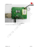
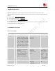
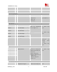
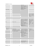
Table Of Contents
- Contents
- Version history
- 1 Introduction
- 2 SIM900B Overview
- 3 Application Interface
- 3.1 SIM900B Pin Description
- 3.2 Operating Modes
- 3.3 Power Supply
- 3.4 Power Up and Power Down Scenarios
- 3.5 Power Saving
- 3.6 Summary of State Transitions (except SLEEP mode)
- 3.7 RTC Backup
- 3.8 Serial Interfaces
- 3.9 Audio Interfaces
- 3.10 Buzzer
- 3.11 SIM Card Interface
- 3.12 LCD Display Interface
- 3.13 Keypad Interface
- 3.14 ADC
- 3.15 Behaviors of the RI
- 3.16 Network Status Indication
- 3.17 General Purpose Input Output (GPIO)
- 4 Antenna Interface
- 5 Electrical, Reliability and Radio Characteristics
- 6 Mechanics

SIM900B Hardware Design
3 Application Interface
SIM900B is equipped with a 60-pin 0.5mm pitch board-to-board connector that connects to the cellular
application platform. Sub-interfaces included in this board-to-board connector are described in detail in following
chapters:
z Power supply (please refer to Chapter 3.3
)
z Serial interfaces (please refer to Chapter 3.8
)
z Analog audio interfaces (please refer to Chapter 3.9
)
z SIM interface (please refer to Chapter 3.11)
Electrical and mechanical characteristics of the board-to-board connector are specified in Chapter 6. There we also
include order information for mating connectors.
3.1 SIM900B Pin Description
Table 5: Pin description
Power Supply
PIN NAME I/O DESCRIPTION DC CHARACTERISTICS COMMENT
VBAT I 8 VBAT pins are dedicated to
connect the supply voltage.
The power supply of SIM900B
has to be a single voltage
source of VBAT= 3.2V...4.8V.
It must be able to provide
sufficient current in a transmit
burst which typically rises to
2A
Vmax= 4.8V
Vmin=3.1V
Vnorm=4.0V
VRTC I/O Current input for RTC when
the battery is not supplied for
the system.
Current output for backup
battery when the main battery
is present and the backup
battery is in low voltage state.
Vmax=3.15V
Vmin=2.0V
Vnorm=3.0V
Iout(max)= 200uA
Iin=3 uA
If the RTC function
is enabled, a
backup battery or
capacitor should be
connected to the
VRTC pin.
Otherwise connect
a 4.7uF capacitor
to the VRTC pin.
VDD_EXT O 2.8V output power supply Vmax=2.95V
Vmin=2.70V
Vnorm=2.80V
If unused, keep
open.
SIM900B_HD_V1.03 24.06.2010
18