
User's Manual

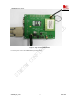
Table Of Contents
- Contents
- Version history
- 1 Introduction
- 2 SIM900B Overview
- 3 Application Interface
- 3.1 SIM900B Pin Description
- 3.2 Operating Modes
- 3.3 Power Supply
- 3.4 Power Up and Power Down Scenarios
- 3.5 Power Saving
- 3.6 Summary of State Transitions (except SLEEP mode)
- 3.7 RTC Backup
- 3.8 Serial Interfaces
- 3.9 Audio Interfaces
- 3.10 Buzzer
- 3.11 SIM Card Interface
- 3.12 LCD Display Interface
- 3.13 Keypad Interface
- 3.14 ADC
- 3.15 Behaviors of the RI
- 3.16 Network Status Indication
- 3.17 General Purpose Input Output (GPIO)
- 4 Antenna Interface
- 5 Electrical, Reliability and Radio Characteristics
- 6 Mechanics

SIM900B Hardware Design
Flash+
SRAM
Baseband
Engine
Radio
Frequency
Board-to-board Connector
LCD
KEYPADS
AUDIO
SIM
ADC
UART
GPIO
POWER
SIM 900B
Antenna
connector
Figure 1: SIM900B functional diagram
2.3 SIM900B Evaluation Board
In order to help you on the application of SIM900B, SIMCom can supply an Evaluation Board (EVB) that
interfaces the SIM900B directly with appropriate power supply, SIM card holder, RS232 serial port, handset port,
earphone port, antenna and all GPIO of the SIM900B.
SIM900B_HD_V1.03 24.06.2010
16