
User Guide

SMT Module RF Reference Design Guide
SMT Module RF Reference Design Guide 6
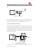
Two-layers PCB is the lowest cost solution, but this solution has the worst EMC performance, and
it is not appropriate in high speed design, because in this solution, the ground integrity, the
crosstalk between signal traces is very bad.
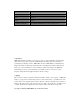
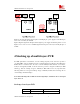
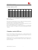
Stack-up of four-layers PCB
Top layer Second layer Third layer Bottom layer
Case A GND S1+POWER S2+POWER GND
Case B S1 GND POWER S2
Table2 Stack-up of four-layers PCB
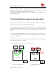
Case A, should be the best case in four-layers PCB board design. In this case, the outer layer is
ground layer, which have some help in shielding the EMI signals; and also, the power supply layer
is very close to the ground layer, so the power supply resistance is smaller, and the EMC
performance will be very good. But if the density of devices on the PCB is very high, then this
type PCB stack-up should not be used to design, because the ground integrity can not be assured
under high density design, and the signal quality in second layer will be very bad. In this situation,
Case B is the most common way usually.
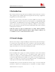
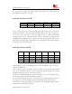
Stack-up of six-layers PCB
Top layer
Second
layer
Third
layer
Fourth
layer
Fifth layer
Bottom
layer
Case A S1 GND S2 S3 POWER S4
Case B S1 S2 GND POWER S3 S4
Case C S1 GND S2 POWER GND S3
Case D GND S1 POWER GND S2 GND
Table3 Stack-up of six-layers PCB
Six-layers PCB gives more design flexibility than a four-layers PCB, but it takes some work to
make it ideal in EMC terms.
Case A in the above table, is the usually common way. In this case, S1 is a better signal routing
layer, and S2 somewhat less. But this case has a disadvantage that this stack-up has very little
distributed capacitance between its ground and power planes.
Case B has good EMC characteristics, because this stack-up has good noise decoupling between
the power plane and ground for the big distributed capacitance.
Case C is the better stack-up, in this case, S1, S2 and S3 are good signal routing layer, the power
decoupling is good for the big distributed capacitance between the ground and power planes.
Case D is the best stack-up, the EMC performance will be good, but the disadvantage is that the
routing layer is less than other type stack-up.