
User Guide

SMT Module RF Reference Design Guide
SMT Module RF Reference Design Guide 3
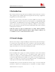
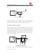
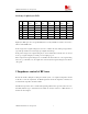
spectrum, switching spectrum, a series large current ferrite bead(with rated current minimum 2A)
should be added at the power supply port. The recommended power supply circuit is shown as
below:
R1
C3
55
SIM900
56
VBAT
VBAT
C2 C1
VBAT
22pF
100nF
100uF
Figure1 Power Supply Circuit
VBAT
57
In this circuit, by default, the component R1 should be a 0ohm resistor with 0805 size. When the
module is powered by DC-DC, and the module’s RF performance is affected by the DC-DC’s
switching frequency, R1 can be changed to a large current ferrite bead to filter the noise.
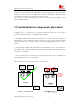
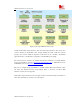
2.2 Antenna matching circuit design
Because the module is working under 50ohm system in RF part, so, to get the best RF
performance, the SMT module’s load impedance should be tuned to 50ohm. But in fact, the most
antenna’s port impedance is not a purely 50ohm, so, to meet the 50ohm requirement, an additional
antenna matching circuit should be needed. Furthermore, to facilitate the antenna debugging and
certification testing of RF performance, we suggested the customer add a RF test connector in
series between the module’s RF port and the antenna matching circuit. The recommended antenna
matching circuit is shown as below:
In the Figure2, the components, R4, C5 and C6 make up a pi-type matching circuit structure. If