
User Guide

SMT Module RF Reference Design Guide
SMT Module RF Reference Design Guide 2
1 Introduction
This document describes the important points about RF that should be taken into account in
client’s application design. As SMT module can be integrated with a wide range of applications,
the application notes are described in detail.
SMT module is a new and key product which is provided by SIMCom inc. This type module
become very popular soon after it is released for its easy integration, good reliability. But bad RF
design will lead to serious RF problems. In order to improve the RF performance, this document is
formed to give the customer some design guides in RF design of SMT type module integration.
Based on such considerations, at the later section, this document will describe some key issues that
should be paid more attention to.
NOTE: this document can apply for all SMT Modules, for example, SIM300D, SIM340D,
SIM300W, SIM340W, SIM500W, SIM540W, SIM700D, SIM900, SIM900A, SIM900D, and
so on. SIM900 is selected as a demonstration in the last sections.
2 Circuit design
When the customer begins to integrate the SMT type module into their product, the first thing to
be considered is the circuit design. In this section, we will focus on the circuit design which is
related to the RF performance. This section is divided into two sub-parts, the first is the power
supply circuit design; the second is the antenna matching circuit design.
2.1 Power supply circuit design
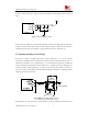
Because the SMT module is a high power consuming communication system, and the maximum
working power will up to 2watt in worst case, so, this will form a large voltage drop at the
module’s power supply port. To make the SMT module have a stabilized working condition, we
recommended a large tantalum capacitor (100uF or more capacity is recommended) shunted to the
module’s power supply port. To get better noise decoupling performance, some additional small
ceramic capacitors can be added combined with the large capacitor.
If the SMT module is powered by a DC-DC in the customer’s design, to avoid the module’s RF
performance is affected by the switching frequency of the DC-DC, for example, modulation