
User Guide
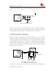

SMT Module RF Reference Design Guide
SMT Module RF Reference Design Guide 8
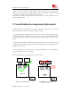
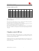
Figure7 twelve typical PCB transmission line
Usually, Surface Mircostrip Transmission Line and offset Strip Transmission Line are the most
common structures. In 50ohm RF system, through adjusting the width of RF traces and the
spacing to the reference GND, the impedance of RF traces can be controlled to 50Ohm.The
appendix will show some illustration in impedance controlled RF trace designing.
The customer may use software tool to calculate the impedance of RF trace, for example CITS25,
released by POLAR, the website is http://www.polarinstruments.com/, or APPCAD released by
AGILENT, the website is http://www.hp.woodshot.com.
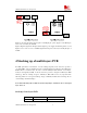
Here are two examples about using CITS25 to calculate, Surface Mircostrip Transmission Line
and Offset strip Transmission Line correspondingly. Based on stack up of six-layers PCB
(thickness =1.0mm) shown in appendix.
Surface Mircostrip Transmission Line, the height is 298um (25+70+203=298um), the thickness is
25um, the result width (w) is 584um, as shown in figure8.