
User's Manual


SIM548C EVB User Guide
SIM548C-EVB_ UGD _V1.01 04.05.2008
23
turned off.
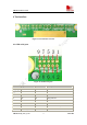
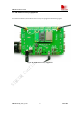
6.1.5 Charging
Connect the SIM548C module to the 60pin connector interface and the external battery to
charging interface, which have been provided on the EVB. Insert the direct current source adapter;
switch shifter S102 on the OFF state, shifter S105 on the ON state, then the SIM548C will go to
the charging state.
6.2 GPS part
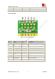
6.1.1 Running:
(1) Connect the module to the 60pins connector on the EVB, insert the 5V direct current source
adapter.
(2) Switch shifter S103 & shifter S104 on the RUN state, shifter S106 on the GPS_TXA state.
(3) Switch shifter S102 & shifter S107 on the ON state, then the GPS part of the module begins to
run.
You will see the GPS indicator (RX/TX_LED) on the EVB glittering at a 1Hz frequency, then you
can judge whether the EVB and the GPS part of the module is running or not. No function and test
can be executed when we have not connected necessary accessories.
Notes:
1.Be sure of both shifter S103 and shifter S104 is on RUN state when the GPS part of SIM548C
is running normally, otherwise the GPS part of the module will be on a undetermined state.
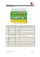
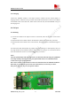
2. There are two types of GPS antenna:
One is active antenna, if the customer uses the active GPS antenna in the SIM548C-EVB kit to
demo GPS, for providing the power to the active GPS antenna, it is necessary to connect
GPS_VANT with GPS_RF_VCC, the picture as below: