Module user manual Module Model :TCPWIFI8710BX-04 Hardware Version:V1.3 Date: 2019-12-05 Draft (Hardware Engineer) Check (Hardware Manager) Approve (Product Line Deputy Manager) Customer Approve Sign in (Project Manager) All rights reserved, contents or specifications are subject to change without prior notice.
Changes Record *A - Add Version Date ( A* M*D) Modifier M - Modify D - Delete Description Remark All rights reserved, contents or specifications are subject to change without prior notice.
Contents 1. Introduction ........................................................................................................................ 4 2. Technical Specifications ..................................................................................................... 5 3. Electrical Property .............................................................................................................. 6 4. Top View and Pins Rank ......................................................................
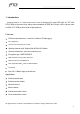
1. Introduction is designed for smart LED light by TCP with RTL8710BX as the main chip, which meets standards of IEEE 802.11b/g/n. Also it can be used on DIM, CCT, RGB or other kinds of light products. TCPWIFI8710BX-04, a 2.
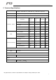
2. Technical Specifications Network Standard Wireless Channel No. Frequency Range IEEE 802.11b IEEE 802.11g 1-11(Channels vary from country to country) 2.412-2.462GHz(Frequency varies from country to country) Test Item Transmit Power EVM Receive Sensitivity IEEE 802.11n(HT20) Minimum Reference Value Value Max Value Unit 802.11b 1M 18 19 19.5 dBm 802.11g 6M, 18 19 19.5 dBm 802.11n(HT20) MCS7 18 19 19.5 dBm Frequency Error -15 - 15 KHZ 802.11b 1M EVM -35 -26 -10 dB 802.
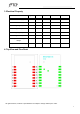
3. Electrical Property Parameters Symbol Minimum Reference Max Unit 3.3V Power supply VDD 3.15 3.3 3.45 V 80 400 mA 3.3V Power consumption Voltage high input VIH 2.8 - 3.6 V Voltage low input VIL -0.3 - 0.3 V Voltage high output VOH 2.2 - 3.45 V Voltage low output VOL 0 0.4 V Output current in high IOH 5 mA IOL 5 mA voltage Output current in low voltage 4.
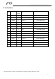
5. Pin Definition Pin Symbol No. Input/ Description RTL8710BX IC Pin NC RTL8710BX_PIN12 Output 2 CHIP_EN I 4 GPIOA_19 I/O GPIO reserved RTL8710BX_PIN30 5 PWM2_B O PWM2_B RTL8710BX_PIN14 6 PWM3_G O PWM3_G RTL8710BX_PIN17 7 PWM5_CT O PWM5_CT RTL8710BX_PIN28 8 VDD O 3.
6. Structure 6 .1 Module Package TOP View 6.2 Module Size 24*16*3.0MM All rights reserved, contents or specifications are subject to change without prior notice.
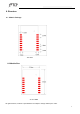
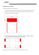
7. Attentions for Antenna Followings are attentions for on-board antenna. 1. Components and GND are not allowed to place in red zone below. It is suggested to be hollow. 2. Metals should be far away from antenna, at lease 10mm away from the highest component. 3. Antenna can not be covered by metal shell. 4. Components are prefer to place in red zone below to reduce the impact to antenna. Also you can ask for technical support about layout design.
8. Regulatory Module Integration Instructions 8.1 List of applicable FCC rules This device complies with part 15.247 of the FCC Rules. 8.2 Summarize the specific operational use conditions This module can be used in household electrical appliances as well as lighting equipments. The input voltage to the module should be nominally 3.0~3.6 VDC ,typical value 3.3VDC and the ambient temperature of the module should not exceed 85 . This module using only one kind of antennas with maximum gain is 0 dBi .
8. 7 Label and compliance information The outside of final products that contains this module device must display a label referring to the enclosed module. This exterior label can use wording such as: “Contains Transmitter Module FCC ID: NIR-WIFI8710 ”,or “Contains FCC ID: NIR-WIFI8710”, Any similar wording that expresses the same meaning may be used. 8.
2. Open" UI_mptool.exe". Firstly, you must “Initialize” the DUT,and then the four sub interface: Main,PSD,Efuse,Reg can be operated. 3. Main: Note: When you select "Initialize with Pidx in EEPROM", a It means that TX Power Index Column A will show the Efuse Index Value, which also have been limited by “Power by rate table ”(limit power by rate in each mode) and “Power limit table ”(limit power by channel plan value) before shown.
The product under test is placed into a normal ‘paired’ mode with another WIFI device, as per the normal intended use of the product (for example, transferring data). FCC Statement Any Changes or modifications not expressly approved by the party responsible for compliance could void the user’s authority to operate the equipment. This device complies with part 15 of the FCC Rules.