
User's Manual
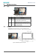

3. Antenna
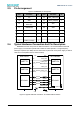
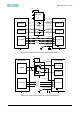
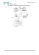
There is co-layout design (C35&C32) for antenna connection. Normally, load the capacitor
c35(10pF/0201) , it means can use U.F.L RF connector for external antenna. If want to use on-
board PCB printed antenna, just need load the capacitor from C35 to C32.
In order to get the maximum performance, strongly suggest customer use external antenna
connected with U.F.L RF connector.
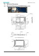
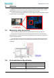
3.1. Minimizing radio interference
When integrating the WiFi module with on board PCB printed antenna, make sure
the area around the antenna end the module protrudes at least 15mm from the mother
board PCB and any metal enclosure. If this is not possible use the on board U.FL connector to
route to an external antenna.
The area (6.5mmx17.3mm) under the antenna end of the module should be keep clear of
metallic components, connectors, vias, traces and other materials that can interfere with the
radio signal.
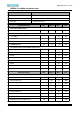
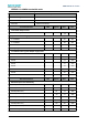
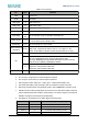
3.2. On-board Antenna Specification
Operating Frequency
2.412~2.472GHz
VSWR (max)
<=2.5:1
Peak Gain
~2.1dBi
Antenna Type
PCB printed PiFA antenna
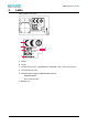
! ! EMW3280 Wi-Fi module
14