
User's Manual
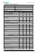
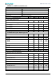
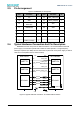
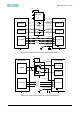
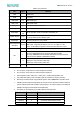
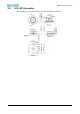

Table 2.3 Pin functions
Pin
Type
Function
VDD
Power input.
GND
Grounding.
UART_RXD
I, FT
UART Data input.
UART_TXD
O
UART Data output.
nUART_CTS
I, FT
UART allow to send, active low.
nUART_RTS
O
UART is ready to receive, active low.
STATUS(IN)
I, FT,
PU
Set the operation mode, cooperation with BOOT pin:
WAKE_UP(IN)
I, PU
•
Pull down: Enter standby mode
•
Pull up: Wake up from standby mode
nRESET(IN)
I, PU
Pull down this pin for 1μs to reboot.
nWI-FI LED(OUT)
BOOT(IN)
O/I, PU
This pin has two functions:
nWIFI_LED:Output led D1 status, Low: D1 = on, High: D1 = off.
BOOT:Enter different operation modes when powered on or reset.
IO1
NC
IO1 can be configured by software
IO1
I
Set to Frame Control mode (FC), used in DTU mode:
Input low, EMW3280 store the received UART data in RAM.
Input high, EMW3280 send the buffed UART data over Wi-Fi network.
Refer document: RM0001_EMW3280 for details
IO1
O
Set to Half-duplex Control mode (HDC), used in DTU mode:
Output low, while receiving UART data
Output high, while sending UART data
NC
Undefined IOs. Leave them floating or grounding.
1. FT: = 5V input tolerant.
2. PU: The pin is at high level if no external signal is asserted.
3. PD: The pin is at low level if no external signal is asserted.
4. UART signals include: UART_TXD,UART_RXD,nUART_RTS和nUART_CTS.
5. Only VDD, GND UART_TXD and UART_RXD are needed in a simple connection.
6. We strong recommend that using STATUS signal to switch EMW3X80’s operation mode.
7. nRESET should not be forced pulled up by external circuit, otherwise standby mode and
internal watchdog would be unable to work properly. If an external signal is connected to
nRESET, this signal must be Open Drain Mode (OD).
8. Use BOOT pin and STATUS pin to define different working mode.
BOOT
STATUS
EMW3280 operation mode
0
0
MFG mode
0
1 (Default)
FW UPDATE mode
1 (Default)
0
Command mode (working mode)
1 (Default)
1 (Default)
DTU mode (working mode)
! ! EMW3280 Wi-Fi module
13