
User's Manual


Application Note [Page 3]
Design Considerations of EMW3239
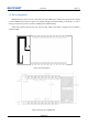
Figure 2.3 SMT Package ..................................................................................................................................... 7
Figure 2.4 PCB Design ........................................................................................................................................ 9
Figure 2.5 Minimum PCB Clearance Area ........................................................................................................ 10
Figure 2.6 Position of the Module ..................................................................................................................... 10
Figure 2.7 Size of External Antenna .................................................................................................................. 11
Figure 3.1Switch Set Up .................................................................................................................................... 13
Figure 3.2Power Light ....................................................................................................................................... 13
Figure 3.3 Name in Device Manager ................................................................................................................. 13
Figure 3.4 Install J-Flash ................................................................................................................................... 14
Figure 3.5 J-Flash signature ............................................................................................................................... 14
Figure 3.6 Target Interface Set Up ..................................................................................................................... 14
Figure 3.7 MCU Set Up ..................................................................................................................................... 15
Figure 3.8 Production Set Up ............................................................................................................................ 15
Figure 3.9 Position of Routers ........................................................................................................................... 16
Figure 4.1 Stencils size ...................................................................................................................................... 17
Figure 4.2 Temperature Curve of Secondary Reflow ........................................................................................ 17
Table Content
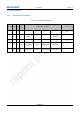
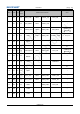
Table 2.1 Switch Mode ........................................................................................................................................ 7
Table 3.1Device List .......................................................................................................................................... 12
Table 3.2Download Websites ............................................................................................................................. 12