
User's Manual

Datasheet [Page 12]
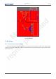
EMW3239
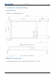
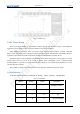
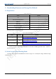
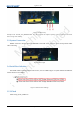
Illustration:
1. Pin 10, pin 39 and pin 40 should be connected to VDD 3V3, pin 20 and pin 21 should be connected to ground;
2. Pin 8 and pin 12 could only be used in secondary write, ATE or QC automatic detection;
3. Pin 29 and pin 30 is used as serial communication in bootloader mode for users;
4. S stands for power supply, I stands for input pins and I/O stands for input and output pins;
5. FT= 5V tolerant, The maximum voltage should be less than VCC when set as analog input/output or clock
oscillation circuit;
6. TC= 3.6V as convention input/output voltage;
7. SWD(pin 25, pin 26) is used to debug and download firmware instead of JTAG;
8. Pins are not available for users with signature “X” while pins with signature “√” is available for users;
9. For other information please contact technical support.