
User's Manual
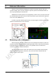
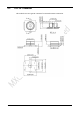
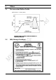
Table Of Contents
- 1 Introduction
- 2 Interface
- 3 Electrical Parameters
- 4 Antenna information
- 5 Others
- 6 Sales Information
- 7 Technical Support

20
4 Antenna information
There is co-layout design (C35&C32) for antenna connection. Please order your
module carefully. Users can also modify the capacitor position but MXCHIP would not
take any responsibility for this behavior.
EMW3161-E load the capacitor C35 (10pF/0201), it means can use U.F.L RF connector
for external antenna. If want to use on-board chip antenna, just need load the capacitor
from C35 to C32 (EMW3161-C).
In order to get the maximum performance, strongly suggest customer use external
antenna connected with U.F.L RF connector.
4.1 Minimizing radio interference
When integrating the Wi-Fi module with on board PCB printed antenna, make sure
the area around the antenna end the module protrudes at least 15mm from the mother
board PCB and any metal enclosure. If this is not possible use the on board U.FL
connector to route to an external antenna.
The area (6.5mmx17.3mm) under the antenna end of the module should be keep
clear of metallic components, connectors, vias, traces and other materials that can
interfere with the radio signal.
15mm
15mm