
User's Manual
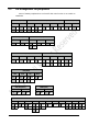
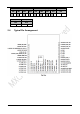
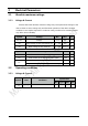
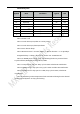
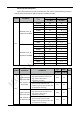
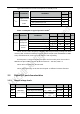
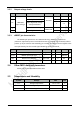
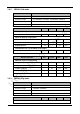
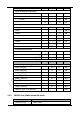
Table Of Contents
- 1 Introduction
- 2 Interface
- 3 Electrical Parameters
- 4 Antenna information
- 5 Others
- 6 Sales Information
- 7 Technical Support

14
3.3.2 Output voltage levels
Symbol Note Parameter Conditions Min. Max. Unit
V
IL
UART& IO
input voltage
Input low level voltage
TTL level
-0.5 0.8 V
V
IH
Input high level voltage 2 VDD+0.5 V
Input high level voltage
(5V input tolerant)
2 5.5 V
V
IL
Input low level voltage
CMOS level
-0.5 0.35VDD V
V
IH
Input high level voltage 0.65VDD VDD+0.5 V
3.3.3 nRESET pin characteristics
The nRESET pin input driver uses CMOS technology. EMW3161 contains RC
(resistance-capacitance) reset circuit which ensures the module reset accurately when it
powers up. If you need to reset manually, just connect the external control signals to the
reset pins directly, but the control signal should be Open Drain Mode。
Symbol Item Conditions Min. Typical Max. Unit
V
IL(NRST)
nRESET input low level
–0.5
0.8
V
V
IH(NRST)
nRESET input high level
2
VDD+0.5
R
PU
Resistor for Pulling up V
IN
= VSS
7.5 8 8.3 kΩ
C
PD
Capacitor for charging and Resetting
100 1000 pF
3.4 Other MCU electrical parameters
Please refer to STM32F215RGT6 data sheet.
3.5 Temperature and Humidity
Symbol Ratings Max Unit
T
STG
Storage temperature –55 to +125
℃
T
A
Working temperature -40 to +85
℃
Humidity Non condensing, relative humidity Max. 95%