
User's Manual
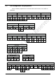
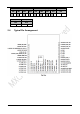
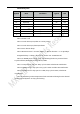
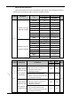
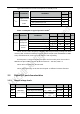
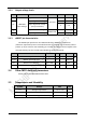
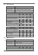
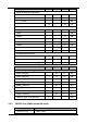
Table Of Contents
- 1 Introduction
- 2 Interface
- 3 Electrical Parameters
- 4 Antenna information
- 5 Others
- 6 Sales Information
- 7 Technical Support

13
Typical and maximum current consumptions in Standby mode
Symbol
Parameter
Conditions
Typ
Unit
T
A
=25°C
I
MCU
Supply current
in Standby
mode
Backup SRAM ON, low-speed oscillator and RTC ON
4.0
μA
Backup SRAM OFF, low-speed oscillator and RTC ON
3.3
Backup SRAM ON, RTC OFF
3.0
Backup SRAM OFF, RTC OFF
2.2
Power consumption in typical operation modes
3
Symbol
Parameter
Conditions
Min
Average
Max
Unit
T
A
=25°C
T
A
=25°C
T
A
=25°C
I
module
Total power
consumption
on EMW3161
module
No Wi-Fi data is transmitting
1
2.8
7.2
73.5
mA
Receive data in UDP mode, 20k bps
1
2.8
12
262
mA
Send data in UDP mode, 20k bps
1
3
24
280
mA
RF off, MCU enter standby mode
2
4
6
8
μA
Connecting to AP
52
74
320
mA
Note1: TA=25°C, MCU frequency=120MHz, with data processing running from Flash
memory (ART accelerator enabled). Firmware process TCP/IP stack and IEEE 802.11 MAC
every 250 milliseconds, enter stop mode when no task is pending.
RF subsystem is connected to an access point and run under power save mode in
IEEE 802.11n@14.5 dBm Tx power. AP Beacon Interval = 102.4ms, DTIM = 1.
Note2: Wi-Fi connection is disconnected.
Note3: These data may not be the same depend on different firmware functions.
3.3 Digital I/O port characteristics
3.3.1 Output voltage levels
Symbol
Note
Parameter
Conditions
Min.
Max.
Unit
V
OL
UART& IO
output voltage
Output low level voltage
I
IO
= +8 mA
2.7 V < VDD < 3.6 V
0.4
V
V
OH
Output high level voltage
V
DD
-0.4
V
V
OL
Output low level voltage
I
IO
= +20 mA
2.7 V < VDD < 3.6 V
1.3
V
V
OH
Output high level voltage
V
DD
-1.3
V