
User's Manual
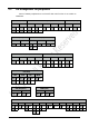
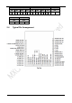
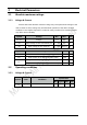
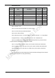
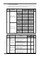
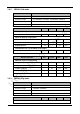
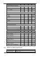
Table Of Contents
- 1 Introduction
- 2 Interface
- 3 Electrical Parameters
- 4 Antenna information
- 5 Others
- 6 Sales Information
- 7 Technical Support

11
WLAN Subsystem
Symbol
Note
Conditions
Typical
Unit
I
RF
OFF
1
2
μA
I
RF
SLEEP
4
200
μA
I
RF
Rx(Listen)
2
52
mA
I
RF
Rx(Active)
3
59
mA
I
RF
Power Save
5 6
1.9
mA
I
RF
Tx CCK
7 10
11 Mbps at 18.5 dBm
320
mA
I
RF
Tx OFDM
8 10
54 Mbps at 15.5 dBm
270
mA
I
RF
Tx OFDM
9 10
65 Mbps at 14.5 dBm
260
mA
Note 1: Power is off.
Note 2: Carrier Sense (CCA) when no carrier present
Note 3: Carrier Sense (CS) detect/Packet Rx
Note 4: Intra-beacon Sleep
Note 5: Beacon Interval = 102.4ms, DTIM = 1, Beacon duration = 1 ms @1 Mbps.
Integrated Sleep + wakeup + Beacon Rx current over 1 DTIM interval.
Note 6: In WLAN power-saving mode, the following blocks are powered down:
Crystal oscillator, Baseband PLL, AFE, RF PLL, Radio
Note 7: CCK power at chip port. Duty cycle is 100%. Includes PA contribution.
Note 8: OFDM power at chip port. Duty cycle is 100%. Includes PA contribution.
Note 9: OFDM power at chip port is 16 dBm, duty cycle is 100%, includes PA
contribution.
Note 10: Absolute junction temperature limits maintained through active thermal
monitoring and dynamic Tx duty cycle limiting.