
User's Manual
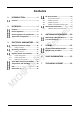
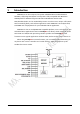
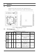
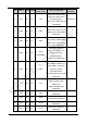
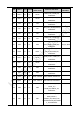
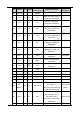
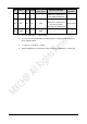
Table Of Contents
- 1 Introduction
- 2 Interface
- 3 Electrical Parameters
- 4 Antenna information
- 5 Others
- 6 Sales Information
- 7 Technical Support

7
Pins
Name
Type
IO level
Main function
(after reset)
Alternate functions
Other
functions
TIM9_CH1 / TIM2_CH3 /
ETH_MDIO/EVENTOUT
48
PA3
(2)
I/O
FT
PA3
USART2_RX/TIM5_CH4 /
TIM9_CH2 / TIM2_CH4 /
OTG_HS_ULPI_D0 /
ETH_MII_COL/ EVENTOUT
ADC123_IN3
49
GND
S
GND
1. FT = 5 V tolerant; TT = 3.6 V tolerant.
2. FT = 5 V tolerant except when in analog mode or oscillator mode (for PC14,
PC15, PH0 and PH1).
3. I = input, O = output, S = supply.
4. STM32 peripherals are not listed if they cannot be presented on current pins