EMW3092 Datasheet Embedded Wi-Fi module Version:1.1 Date:2019-03-20 Number: DS0132EN Abstract Features ⚫ Support 802.11b/g/n, integrate ARMCM4F, WLAN MAC/Baseband/RF ⚫ 256KB RAM/ 2MB FLASH ⚫ Working Voltage: DC 3.0-3.6V ⚫ Maximum transmission rate up to 65 Mbps with 20 MHz bandwidth. ⚫ EMW3092: EMW3092L: -20℃ to +85℃ -20℃ to +105℃ Application ⚫ Intelligent lighting ⚫ Smart Home Application Wi-Fi Features ⚫ Industrial automation ▪ ⚫ Intelligent Security Support 802.
Datasheet Version History Date Version Details 2019-03-20 1.0 Initial release 2019-03-21 1.
Datasheet Content Abstract ................................................................................................................................................................................. 1 Version History ..................................................................................................................................................................... 1 1. Product Introduction................................................................................................
Datasheet Figure 5 Package Definition ........................................................................................................................... 6 Figure 6 PCB antenna minimum clearance area (unit: mm)........................................................................... 13 Figure 7 Humidity Card ............................................................................................................................... 14 Figure 8 Storage Condition ..................................
Datasheet 1. Product Introduction EMW3092 is a cost-effective embedded Wi-Fi module released by MXCHIP with high integrating ARM CM4F, WLAN MAC/Baseband/RF. Maximum frequency 62.5MHz with 256KB SRAM and 2M FLASH. Power supply is DC 3.3V. Hardware diagram is shown below with four main parts: ⚫ CM4F main core ⚫ WLAN MAC/BB/RF/ANT ⚫ Hardware encryption ⚫ Power management With: 1. ARM CM4F CPU with 62.5MHz maximum frequency and 256KB SRAM and 2M FLASH.
Datasheet This device complies with part 15 of the FCC Rules. Operation is subject to the following two conditions: (1) This device may not cause harmful interference, and (2) this device must accept any interference received, including interference that may cause undesired operation. Pin Arrangement EMW3092 adopts a through-hole and SMT package design. The stamp hole package design is convenient for customer debugging, easy to disassemble and easy to use for SMT. The left and right pads are 1.2x1.
Datasheet Figure 4 SMT Package Size Pin Definition 1.3.1 EMW3092 Package Definition Figure 5 Package Definition 1.3.2 EMW3092 Pin Definition EMW3092 Pin Definition is shown as Table 1.
Datasheet Pin FUNCTION1 FUNCTION2 FUNCTION3 14 MICO_GPIO_1 15 MICO_GPIO_10 MICO_I2C1_CLK MICO_UART0_RXD 16 MICO_GPIO_9 MICO_I2C1_SDA MICO_UART0_TXD 17 MICO_GPIO_19 FUNCTION4 MICO_PWM1 FUNCTION5 SWD_CLK MICO_SPI1_CLK MICO_PWM1 MICO_SPI1_MOSI BOOT Description: (1) The GPIO19 pin defaults to BOOT; the GPIO23 pin is used by EASYLINK; the PIN11/12 pin is used for debugging log information output. Please try not to use the hardware design. Please contact our engineers for confirmation.
Datasheet 2. Electrical Parameters Operating Conditions EMW3092 would be unstable when input voltage is less than the lowest rated voltage. Table 1 Range of input voltage Details Symbol VDD Illustration Condition Minimum Typ Maximum Unit 3.0 3.3 3.6 V Power Supply There would be permanent damage in hardware if the device operates at the voltage over rated value. Meanwhile, reliability could be influenced when the device has a long-term operating at maximum voltage.
Datasheet 4.642 uA Standby 20.323 uA MCU/RAM/Peripherals/RTC OFF, wake up by IO or internal Timer Iperf 115.697mA 345.190mA Wi-Fi and MCU low power mode OFF Iperf 115.030mA 353.832mA Wi-Fi and MCU low power mode ON Actual working current is variable at different operating mode.
Datasheet 3. RF parameters Basic RF parameters Table 6 Radio-frequency standards Name Illustration Working frequency 2.412~2.484GHz Wi-Fi wireless standard IEEE802.11b/g/n 11b:1,2,5.5 和 11Mbps Data 20MHz transmission rate 11g : 6,9,12,18,24,36,48,54Mbps 11n : MCS0~7,72.2Mbps Antenna type PCB (Default) IPX (Optional) TX Performance 3.2.1 Transmit performance of IEEE802.11b mode Table 7 CCK_11 transmit performance parameters of IEEE802.11b mode Category Content Mode IEEE802.
Datasheet 3.2.2 Transmit performance of IEEE802.11g mode Table 8 OFDM_54 transmit performance parameters of IEEE802.11g mode Category Content Mode IEEE802.11g Channel CH1 to CH13 Rate 6, 9, 12, 18, 24, 36, 48, 54Mbps TX Minimum Typ Maximum Unit 1. Output Power 12.5 14.5 16.5 dBm 1) at fc +/- 11MHz - - -20 dBr 2) at fc +/- 20MHz - - -28 dBr -40 dBr 2. Spectrum template 3) at fc > +/-30MHz 3.
Datasheet 1) at fc +/- 11MHz - - -20 dBr 2) at fc +/- 20MHz - - -28 dBr -45 dBr 3) at fc > +/-30MHz 3. Frequency offset -15 -2 +15 ppm - -30 -5 dBm - -32 -27 dBm 4.
Datasheet 4. Antenna Information Type of Antenna EMW3092 is a PCB on-board antenna. Please pay attention to the module PCB onboard antenna clearance area while using. PCB antenna clearance area When using a PCB antenna on a WIFI module, you need to ensure that the distance between the motherboard PCB and other metal components is at least 16mm.
Datasheet 5. Assembly Information and Production Guidance Production Guidance ⚫ The stamp hole package module produced by Mxchip must completely being patched by SMT machine in 24 hours after open firmware package. Otherwise the module should be re-package by vacuum pumping and drying before patch.
Datasheet ▪ 12 hours drying for module if the color ring at 30%, 40%, 50% in humidity indicator card is pink after unpacking. ⚫ Drying parameters: ▪ Drying temperature: 125℃±5℃; ▪ Alarm temperature: 130℃; ▪ SMT patch when the device cool down below 36℃ in natural condition; ▪ Dry times: 1; ▪ Please dry again if the module is unsoldering in 12 hours after last drying. ⚫ SMT is unsuitable if the module packed over 3 months.
Datasheet Storage Condition Figure 8 Storage Condition 16 / 21
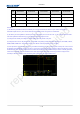
Datasheet Temperature Curve of Secondary Reflow Suggested solder paste type: SAC305, unleaded, solder paste thickness from 0.12 to 0.15, less than 2 times reflow.
Datasheet 6. FCC& IC Information FCC Warning Any Changes or modifications not expressly approved by the party responsible for compliance could void the user's authority to operate the equipment. Note: This equipment has been tested and found to comply with the limits for a Class B digital device, pursuant to part 15 of the FCC Rules. These limits are designed to provide reasonable protection against harmful interference in a residential installation.
Datasheet ⚫ OEM integrators is responsible for ensuring that the end-user has no manual instructions to remove or install module. ⚫ Module is limited to installation in mobile or fixed applications, according to Part 2.1091(b). ⚫ Separate approval is required for all other operating configurations, including portable configurations with respect to Part 2.1093 and different antenna configurations. ⚫ Labeling instructions of finished products.
Datasheet 7. Sales Information and Technical Support For consultation or purchase the product, please contact Mxchip during working hours: From Monday to Friday, morning 9:00~12:00, afternoon 13:00~18:00 Telephone: +86-21-52655026 Contact address: 9thFloor, No.5, Lane2145 JinshaJiang Road Putuo District, ShangHai. Postcode:200333 Email: sales@mxchip.