
Data Sheet

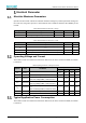


Table Of Contents
- Abstract
- 1. Introduction
- 2. Pin Definition
- 3. Memory Space Allocation
- 4. Work Mode Selection
- 5. Electrical Parameter
- 6. Antenna Information
- 7. Assembly Size and PCB Package
- 8. Reference Circuits and Typical Applications
- 9. FCC and IC Information
- 10. Production Guidelines
- Appendix 1: Sales and Technical Support Information

EMW3076 Series Wireless Module Data Manual
Copyright of Shanghai MXCHIP Information Technology Co., Ltd.
11
Figure 11 USB to Serial Port Typical Circuit
If the host uses 5V power supply and the high-level signal of the serial port is 5V, you need to convert
5V to 3.3V before connecting to the module. A typical circuit is shown in Figure 25:
Figure 12 5V UART Signal Conversion Circuit
Intelligent Lighting
The EMW3076 module can control the brightness of LED lights of various colors through the PWM
function of IO, and realize the display of various colors and cool and warm colors. The PWM signal can
be connected to any color LED, but if you connect according to the specifications shown in Figure 26,
you can use the smart lighting firmware provided by MXCHIP to speed up the time to market.
Figure 13 Intelligent Lighting Application Block
Among them,
If the PWM output signal is externally connected to the LED, it needs to be grounded through a 6K
resistor; if it is not connected to the LED, it will be left floating. When the module is running, it will
automatically detect the channel of the connected LED light to achieve the corresponding function.