
Data Sheet

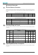


Table Of Contents
- Abstract
- 1. Introduction
- 2. Pin Definition
- 3. Memory Space Allocation
- 4. Work Mode Selection
- 5. Electrical Parameter
- 6. Antenna Information
- 7. Assembly Size and PCB Package
- 8. Reference Circuits and Typical Applications
- 9. FCC and IC Information
- 10. Production Guidelines
- Appendix 1: Sales and Technical Support Information

EMW3076 Series Wireless Module Data Manual
Copyright of Shanghai MXCHIP Information Technology Co., Ltd.
10
Reference Circuits and Typical Applications
IoT Wi-Fi Data Transmission
The module transmits data through the serial port and the device, and after connecting to the Internet
through Wi-Fi, the data is transmitted to the Internet of Things cloud service to realize data collection
and remote control. The system block diagram of the application is as follows:
Figure 9 Wi-Fi data Transmission Typical Application Block Diagram
Among them,
⚫ UART0 is used to transfer application data to the host, and UART1 is used for debugging
information output and debugging command input.
⚫ The SWD interface can use the emulator to debug and download the firmware in the EMW3076
module.
⚫ After the BOOT signal is grounded and powered up, the module can enter the boot program.
In the bootloader, the firmware in the EMW3076 module can be updated via the serial port
(UART0/1).
VDD is decoupled by a 10uF (16V) capacitor. A typical 5V to 3.3V supply is shown in Figure 23:
Figure 10 5V to 3.3V Power Supply Typical Circuit
Through the USB to serial port circuit, you can connect to the PC via USB and interact with the module
through the serial port terminal. The typical circuit is shown in Figure 24: