
Data Sheet

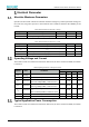


Table Of Contents
- Abstract
- 1. Introduction
- 2. Pin Definition
- 3. Memory Space Allocation
- 4. Work Mode Selection
- 5. Electrical Parameter
- 6. Antenna Information
- 7. Assembly Size and PCB Package
- 8. Reference Circuits and Typical Applications
- 9. FCC and IC Information
- 10. Production Guidelines
- Appendix 1: Sales and Technical Support Information

EMW3076 Series Wireless Module Data Manual
Copyright of Shanghai MXCHIP Information Technology Co., Ltd.
4
Electrical Parameter
Absolute Maximum Parameters
Operation of the module outside of its absolute maximum ratings may result in permanent damage. At
the same time, long-term exposure to the maximum rated conditions will affect the reliability of the
module.
Table 6 Absolute Maximum Parameter:Voltage
Symbol
Ratings
Min
Max
Unit
V
DD
–V
SS
Voltage
–0.3
3.6
V
V
IN
Input voltage on any other pin
V
SS
−0.3
V
DD
+0.3
V
Table 7 Absolute Maximum Parameter:Current
Symbol
Ratings
Max
Unit
I
VDD
Total current into V
DD
power lines (source)
TBD
mA
I
VSS
Total current out of V
SS
ground lines (sink)
TBD
mA
I
IO
Output current sunk by any I/O and control pin
TBD
mA
I
IO
Output current source by any I/O and control pin
TBD
mA
Operating Voltage and Current
The module current test environment is based on VDD=3.3V, the CPU is clocked at 52MHz, and UART1
is turned on.
Table 8 Operating Parameter:Voltage and Current
Symbol
Note
Conditions
Specification
Min.
Typical
Max.
Unit
V
DD
Voltage
2.7
3.3
3.6
V
I
VDD
RX Current
V
DD
=3.3V,CPU@52MHz,UART1 enable
64.29
66.94
71.83
mA
I
VDD
TX Current
V
DD
=3.3V,CPU@52MHz,UART1 enable,
802.11b 11M@18dBm, continuous send
271.86
mA
I
VDD
TX Current
V
DD
=3.3V,CPU@52MHz,UART1 enable,
802.11g 54M@15dBm, continuous send
240.23
mA
I
VDD
TX Current
V
DD
=3.3V,CPU@52MHz,UART1 enable,
802.11n MCS7@13dBm, continuous send
216.41
mA
I
VDD
RF Idle
V
DD
=3.3V,CPU@52MHz,UART1 enable
9.58
9.59
13.43
mA
I
VDD
Standby
V
DD
=3.3V
31.20
31.47
36.41
uA
Typical Application Power Consumption
The module current test environment is based on VDD=3.3V, the CPU is clocked at 52MHz, and UART1
is turned on.