
Data Sheet

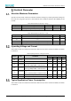


Table Of Contents
- Abstract
- 1. Introduction
- 2. Pin Definition
- 3. Memory Space Allocation
- 4. Work Mode Selection
- 5. Electrical Parameter
- 6. Antenna Information
- 7. Assembly Size and PCB Package
- 8. Reference Circuits and Typical Applications
- 9. FCC and IC Information
- 10. Production Guidelines
- Appendix 1: Sales and Technical Support Information

EMW3076 Series Wireless Module Data Manual
Copyright of Shanghai MXCHIP Information Technology Co., Ltd.
3
⚫ ATE: Runs the RF test mode, in which the RF transmit power, receive sensitivity, and RF parameters
can be tested. Interact with the ATE command using UART1 (P2, P3).
⚫ QC: Run the factory test mode, output QC information through UART0 (P0, P1), and cooperate with
the detection program running on the PC, which can be used to verify the firmware version of the
module, the login information of the cloud service and the basic hardware functions.
When detecting the pin state, the firmware first sets the mode of P11, P12, and P13 to the input pull-up.
Therefore, if the external does not interfere, the read IO state is high, and the default working state is:
Normal.
Table 5 Firmware Working Mode Selection
Firmware working mode
P11(STATUS)
P12(BOOT)
P13(EASYLINK)
Normal
No Detection
1
No Detection
Bootloader
1
0
No Detection
ATE
1
0
0
QC
0
0
No Detection