
Data Sheet

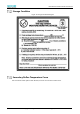
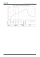


Table Of Contents
- Abstract
- 1. Introduction
- 2. Characteristics
- 3. Pin Definition
- 4. System memory Space
- 5. ATE(RF Test Mode)
- 5.1. Wi-Fi ATE Command
- 5.1.1. Start MP mode
- 5.1.2. Stop MP mode
- 5.1.3. Set Tx rate
- 5.1.4. Set operational channel
- 5.1.5. Set operational bandwidth
- 5.1.6. Set Tx power
- 5.1.7. Set antenna for Tx
- 5.1.8. Set antenna for Rx
- 5.1.9. Start air Rx mode
- 5.1.10. Start continuous Tx mode
- 5.1.11. Query air Rx statistics
- 5.1.12. Reset air Tx/Rx statistics
- 5.2. Bluetooth ATE Command(TBD)
- 5.3. Example Command
- 5.1. Wi-Fi ATE Command
- 6. Flash Programming
- 7. Electrical Parameters
- 8. RF Parameter
- 9. Antenna Information
- 10. Dimensions and Production Guidance
- 11. Production Guidelines
- 12. FCC and IC Information
- 12.1. FCC Warning
- 12.2. IC warning
- 12.3. Trace antenna designs
- 12.4. RF exposure considerations
- 12.5. Antennas
- 12.6. Label and compliance information
- 12.7. Information on test modes and additional testing requirements5
- 12.8. Additional testing, Part 15 Subpart B disclaimer
- 12.9. The module is limited to OEM installation ONLY.
- 12.10. The OEM integrator is responsible for ensuring that the end-user has no manual instructions to remove or install module.
- 12.11. The module is limited to installation in mobile or fixed applications
- 13. Packaging and Label Information
- 14. Sales and Technical Support Information

EMC3380 Series Wireless Module Data Manual
Copyright of Shanghai MXCHIP Information Technology Co., Ltd.
52
Explanation: This module complies with FCC RF radiation exposure limits set forth for an uncontrolled
environment, This equipment should be installed and operated with a minimum distance of 20
centimeters between the radiator and your body." This module is designed to comply with the FCC
statement, FCC ID is: P53-EMC3380.
Antennas
A list of antennas included in the application for certification must be provided in the instructions. For
modular transmitters approved as limited modules, all applicable professional installer instructions must
be included as part of the information to the host product manufacturer. The antenna list shall also
identify the antenna types (monopole, PIFA, dipole, etc. (note that for example an
“omni-directional antenna” is not considered to be a specific “antenna type”)).
For situations where the host product manufacturer is responsible for an external connector, for example
with an RF pin and antenna trace design, the integration instructions shall inform the installer that unique
antenna connector must be used on the Part 15 authorized transmitters used in the host product. The
module manufacturers shall provide a list of acceptable unique connectors.
Explanation: The EUT has a PCB Antenna, , and the antenna use a permanently attached antenna which
is unique.
Label and compliance information
Grantees are responsible for the continued compliance of their modules to the FCC rules. This includes
advising host product manufacturers that they need to provide a physical or e-label stating “Contains
FCC ID” with their finished product. See Guidelines for Labeling and User Information for RF Devices –
KDB Publication 784748.
Explanation: The host system using this module, should have label in a visible area indicated the following
texts: "Contains FCC ID: P53-EMC3380.
Information on test modes and additional testing
requirements5
Additional guidance for testing host products is given in KDB Publication 996369 D04 Module Integration
Guide. Test modes should take into consideration different operational conditions for a stand-alone
modular transmitter in a host, as well as for multiple simultaneously transmitting modules or other
transmitters in a host product.
The grantee should provide information on how to configure test modes for host product evaluation for
different operational conditions for a stand-alone modular transmitter in a host, versus with multiple,
simultaneously transmitting modules or other transmitters in a host.
Grantees can increase the utility of their modular transmitters by providing special means, modes, or
instructions that simulates or characterizes a connection by enabling a transmitter. This can greatly
simplify a host manufacturer’s determination that a module as installed in a host complies with FCC
requirements.