
Data Sheet

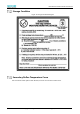
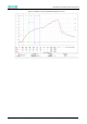


Table Of Contents
- Abstract
- 1. Introduction
- 2. Characteristics
- 3. Pin Definition
- 4. System memory Space
- 5. ATE(RF Test Mode)
- 5.1. Wi-Fi ATE Command
- 5.1.1. Start MP mode
- 5.1.2. Stop MP mode
- 5.1.3. Set Tx rate
- 5.1.4. Set operational channel
- 5.1.5. Set operational bandwidth
- 5.1.6. Set Tx power
- 5.1.7. Set antenna for Tx
- 5.1.8. Set antenna for Rx
- 5.1.9. Start air Rx mode
- 5.1.10. Start continuous Tx mode
- 5.1.11. Query air Rx statistics
- 5.1.12. Reset air Tx/Rx statistics
- 5.2. Bluetooth ATE Command(TBD)
- 5.3. Example Command
- 5.1. Wi-Fi ATE Command
- 6. Flash Programming
- 7. Electrical Parameters
- 8. RF Parameter
- 9. Antenna Information
- 10. Dimensions and Production Guidance
- 11. Production Guidelines
- 12. FCC and IC Information
- 12.1. FCC Warning
- 12.2. IC warning
- 12.3. Trace antenna designs
- 12.4. RF exposure considerations
- 12.5. Antennas
- 12.6. Label and compliance information
- 12.7. Information on test modes and additional testing requirements5
- 12.8. Additional testing, Part 15 Subpart B disclaimer
- 12.9. The module is limited to OEM installation ONLY.
- 12.10. The OEM integrator is responsible for ensuring that the end-user has no manual instructions to remove or install module.
- 12.11. The module is limited to installation in mobile or fixed applications
- 13. Packaging and Label Information
- 14. Sales and Technical Support Information

EMC3380 Series Wireless Module Data Manual
Copyright of Shanghai MXCHIP Information Technology Co., Ltd.
47
If the disassembly time exceeds 3 months, SMT process is forbidden to weld this batch of modules,
because PCB gold deposition process, over 3 months, pad oxidation is serious, SMT patch is likely to lead
to virtual welding, leak welding, resulting in various problems, our company does not assume the
corresponding responsibility;
Before SMT patch, ESD (Electrostatic Discharge, Electrostatic Release) protection should be applied to
the module.
SMT patches should be made according to the reflow curve. The peak temperature is 250 C. The reflow
temperature curve is shown in Chapter 9, Figure 16.
In order to ensure the qualified rate of reflow soldering, 10% of the first patches should be taken for
visual inspection and AOI testing to ensure the rationality of furnace temperature control, device
adsorption mode and placement mode, and 5-10 patches per hour are recommended for visual
inspection and AOI testing in subsequent batch production.
Precautions
⚫ Operators of each station must wear static gloves during the entire production process;
⚫ Do not exceed the baking time when baking;
⚫ It is strictly forbidden to add explosive, flammable or corrosive substances during baking;
⚫ When baking, the module uses a high temperature tray to be placed in the oven to keep the air
circulation between each module while avoiding direct contact between the module and the inner
wall of the oven;
⚫ When baking, please close the oven door to ensure that the oven is closed to prevent temperature
leakage and affect the baking effect.
⚫ Try not to open the door when the oven is running. If it must be opened, try to shorten the time for
opening the door;
⚫ After baking, the module should be naturally cooled to <36°C before wearing the static gloves to
avoid burns;
⚫ When operating, strictly guard against water or dirt on the bottom of the module;
The temperature and humidity control level of MXCHIP factory module is Level3, and the storage and
baking conditions are based on IPC/JEDEC J-STD-020.