
Data Sheet
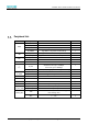
Table Of Contents
- Abstract
- 1. Introduction
- 2. Characteristic
- 3. Pin Definition
- 4. System memory space
- 5. ATE(RF Test Mode)
- 5.1. ATE Command
- 5.1.1. Start MP mode
- 5.1.2. Stop MP mode
- 5.1.3. Set Tx rate
- 5.1.4. Set operational channel
- 5.1.5. Set operational bandwidth
- 5.1.6. Set Tx power
- 5.1.7. Set antenna for Tx
- 5.1.8. Set antenna for Rx
- 5.1.9. Start air Rx mode
- 5.1.10. Start continuous Tx mode
- 5.1.11. Query air Rx statistics
- 5.1.12. Reset air Tx/Rx statistics
- 5.2. Example Command
- 5.1. ATE Command
- 6. Flash Programing
- 7. Electrical parameters
- 8. Antenna Information
- 9. Assembly size and PCB package
- 10. Production Guidelines
- 11. FCC and IC Information
- 11.1. FCC Warning
- 11.2. IC warning
- 11.3. Trace antenna designs
- 11.4. RF exposure considerations
- 11.5. Antennas
- 11.6. Label and compliance information
- 11.7. Information on test modes and additional testing requirements5
- 11.8. Additional testing, Part 15 Subpart B disclaimer
- 11.9. The module is limited to OEM installation ONLY.
- 11.10. The OEM integrator is responsible for ensuring that the end-user has no manual instructions to remove or install module.
- 11.11. The module is limited to installation in mobile or fixed applications
- 12. Package and Label
- Appendix 1: Sales and Technical Support Information

EMC328x Series Wireless Module Data Manual
Copyright of Shanghai MXCHIP Information Technology Co., Ltd.
3
Table 14 RF Parameters .................................................................................................................................................. 24
Table 15 On-board PCB Antenna Parameter of EMC3280 ........................................................................................ 26
Table 16 Typical furnace temperature setting ............................................................................................................ 32
Table 17 MOQ and Package Information .................................................................................................................... 39
Figure Catalog
Figure 1 EMC328x Hardware Block ................................................................................................................................ 2
Figure 2 EMC3280 Pin Arrangement .............................................................................................................................. 8
Figure 3 EMC3285 Pin Arrangement .............................................................................................................................. 8
Figure 4 ATE Mode Connection Diagram .................................................................................................................... 15
Figure 5 JLink Connection Diagram ............................................................................................................................. 19
Figure 6 Connection Diagram of Serial Port Download mode ................................................................................ 20
Figure 7 Use MXKIT-Base to Enter Serial Port Download Mode ............................................................................. 20
Figure 8 Image Tool Interface ....................................................................................................................................... 21
Figure 9 BAT Burning System ........................................................................................................................................ 22
Figure 10 PCB Antenna minimum clearance area(unit:mm) ............................................................................. 26
Figure 11 Copper tube antenna size ............................................................................................................................ 27
Figure 12 External antenna connector size chart ....................................................................................................... 27
Figure 13 EMC3280 three view(unit:mm, error: ±0.1) ....................................................................................... 28
Figure 14 EMC3285 three view(unit:mm) ............................................................................................................. 29
Figure 15 EMC3280 PCB Package size(unit:mm)................................................................................................. 29
Figure 16 EMC3285 PCB Package size(unit:mm)................................................................................................. 30
Figure 17 Humidity Card ................................................................................................................................................ 31
Figure 18 Typical secondary reflow profile ................................................................................................................. 33
Figure 19 Storage Condition Diagram ......................................................................................................................... 34
Figure 20 EMC3285 Product Label ............................................................................................................................... 39