
Data Sheet
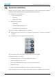
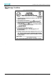

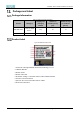

Table Of Contents
- Abstract
- 1. Introduction
- 2. Characteristic
- 3. Pin Definition
- 4. System memory space
- 5. ATE(RF Test Mode)
- 5.1. ATE Command
- 5.1.1. Start MP mode
- 5.1.2. Stop MP mode
- 5.1.3. Set Tx rate
- 5.1.4. Set operational channel
- 5.1.5. Set operational bandwidth
- 5.1.6. Set Tx power
- 5.1.7. Set antenna for Tx
- 5.1.8. Set antenna for Rx
- 5.1.9. Start air Rx mode
- 5.1.10. Start continuous Tx mode
- 5.1.11. Query air Rx statistics
- 5.1.12. Reset air Tx/Rx statistics
- 5.2. Example Command
- 5.1. ATE Command
- 6. Flash Programing
- 7. Electrical parameters
- 8. Antenna Information
- 9. Assembly size and PCB package
- 10. Production Guidelines
- 11. FCC and IC Information
- 11.1. FCC Warning
- 11.2. IC warning
- 11.3. Trace antenna designs
- 11.4. RF exposure considerations
- 11.5. Antennas
- 11.6. Label and compliance information
- 11.7. Information on test modes and additional testing requirements5
- 11.8. Additional testing, Part 15 Subpart B disclaimer
- 11.9. The module is limited to OEM installation ONLY.
- 11.10. The OEM integrator is responsible for ensuring that the end-user has no manual instructions to remove or install module.
- 11.11. The module is limited to installation in mobile or fixed applications
- 12. Package and Label
- Appendix 1: Sales and Technical Support Information

EMC328x Series Wireless Module Data Manual
Copyright of Shanghai MXCHIP Information Technology Co., Ltd.
36
✓ (2) l'utilisateur de l'appareildoit accepter tout brouillageradioélectriquesubi, mêmesi le
brouillageest susceptible d'encompromettre le fonctionnement.
Trace antenna designs
For a modular transmitter with trace antenna designs, see the guidance in Question 11 of KDB Publication
996369 D02 FAQ – Modules for Micro-Strip Antennas and traces. The integration information shall
include for the TCB review the integration instructions for the following aspects: layout of trace design,
parts list (BOM), antenna, connectors, and isolation requirements.
a) Information that includes permitted variances (e.g., trace boundary limits, thickness, length, width,
shape(s), dielectric constant, and impedance as applicable for each type of antenna);
b) Each design shall be considered a different type (e.g., antenna length in multiple(s) of frequency,
the wavelength, and antenna shape (traces in phase) can affect antenna gain and must be considered);
c) The parameters shall be provided in a manner permitting host manufacturers to design the printed
circuit (PC) board layout;
d) Appropriate parts by manufacturer and specifications;
e) Test procedures for design verification; and
f) Production test procedures for ensuring compliance.
The module grantee shall provide a notice that any deviation(s) from the defined parameters of the
antenna trace, as described by the instructions, require that the host product manufacturer must notify
the module grantee that they wish to change the antenna trace design. In this case, a Class II permissive
change application is required to be filed by the grantee, or the host manufacturer can take responsibility
through the change in FCC ID (new application) procedure followed by a Class II permissive change
application.
Explanation: Yes, The module with trace antenna designs, and This manual has been shown the layout of
trace design,, antenna, connectors, and isolation requirements.
RF exposure considerations
It is essential for module grantees to clearly and explicitly state the RF exposure conditions that permit
a host product manufacturer to use the module. Two types of instructions are required for RF exposure
information: (1) to the host product manufacturer, to define the application conditions (mobile, portable
– xx cm from a person’s body); and (2) additional text needed for the host product manufacturer to
provide to end users in their end-product manuals. If RF exposure statements and use conditions are not
provided, then the host product manufacturer is required to take responsibility of the module through a
change in FCC ID (new application).
Explanation: This module complies with FCC RF radiation exposure limits set forth for an uncontrolled
environment, This equipment should be installed and operated with a minimum distance of 20
centimeters between the radiator and your body." This module is designed to comply with the FCC
statement, FCC ID is: P53-EMC3280.