
Data Sheet
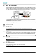
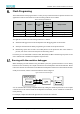
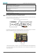
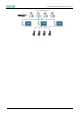
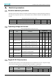
Table Of Contents
- Abstract
- 1. Introduction
- 2. Characteristic
- 3. Pin Definition
- 4. System memory space
- 5. ATE(RF Test Mode)
- 5.1. ATE Command
- 5.1.1. Start MP mode
- 5.1.2. Stop MP mode
- 5.1.3. Set Tx rate
- 5.1.4. Set operational channel
- 5.1.5. Set operational bandwidth
- 5.1.6. Set Tx power
- 5.1.7. Set antenna for Tx
- 5.1.8. Set antenna for Rx
- 5.1.9. Start air Rx mode
- 5.1.10. Start continuous Tx mode
- 5.1.11. Query air Rx statistics
- 5.1.12. Reset air Tx/Rx statistics
- 5.2. Example Command
- 5.1. ATE Command
- 6. Flash Programing
- 7. Electrical parameters
- 8. Antenna Information
- 9. Assembly size and PCB package
- 10. Production Guidelines
- 11. FCC and IC Information
- 11.1. FCC Warning
- 11.2. IC warning
- 11.3. Trace antenna designs
- 11.4. RF exposure considerations
- 11.5. Antennas
- 11.6. Label and compliance information
- 11.7. Information on test modes and additional testing requirements5
- 11.8. Additional testing, Part 15 Subpart B disclaimer
- 11.9. The module is limited to OEM installation ONLY.
- 11.10. The OEM integrator is responsible for ensuring that the end-user has no manual instructions to remove or install module.
- 11.11. The module is limited to installation in mobile or fixed applications
- 12. Package and Label
- Appendix 1: Sales and Technical Support Information

EMC328x Series Wireless Module Data Manual
Copyright of Shanghai MXCHIP Information Technology Co., Ltd.
15
ATE(RF Test Mode)
According to the description of Table 4 firmware special function capture pin table 4, after the module is
booted into ATE mode, the module can enter the specific transceiver mode through the debugging serial
port (UART_LOG) and the module interaction, thus the RF and electrical performance. carry out testing.
Figure 4 ATE Mode Connection Diagram
If you use the MXKIT series evaluation board provided by MXCHIP, the BOOT signal on the DIP switch on
the MXKIT-BASE board can be turned to the ON end.
PC serial terminal setting parameters: baud rate 115200, 8 data bits, 1 stop bit, no parity. The currently
supported ATE commands are as follows:
ATE Command
5.1.1. Start MP mode
After executing this command, the Wi-Fi driver stops transmitting data and enters MP mode
iwpriv mp_start
5.1.2. Stop MP mode
After the command is executed, the Wi-Fi driver stops the transmission of messages opened by other
commands. But the system needs to be restarted, and it can enter the normal Wi-Fi connection mode.
iwpriv mp_stop
5.1.3. Set Tx rate
Set the data transmission rate of Tx packets.
iwpriv mp_rate rate
rate: data transmission rate,2 = 1M, 4 = 2M, 11 = 5.5M, …, 108 = 54M, 128 = MCS0, 129 = MCS1, …,
142 = MCS15
5.1.4. Set operational channel
Set the working frequency band for sending and receiving packets.
iwpriv mp_channel channel
channel: Frequency band for sending and receiving messages