
Data Sheet

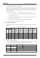
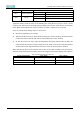
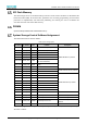
Table Of Contents
- Abstract
- 1. Introduction
- 2. Characteristic
- 3. Pin Definition
- 4. System memory space
- 5. ATE(RF Test Mode)
- 5.1. ATE Command
- 5.1.1. Start MP mode
- 5.1.2. Stop MP mode
- 5.1.3. Set Tx rate
- 5.1.4. Set operational channel
- 5.1.5. Set operational bandwidth
- 5.1.6. Set Tx power
- 5.1.7. Set antenna for Tx
- 5.1.8. Set antenna for Rx
- 5.1.9. Start air Rx mode
- 5.1.10. Start continuous Tx mode
- 5.1.11. Query air Rx statistics
- 5.1.12. Reset air Tx/Rx statistics
- 5.2. Example Command
- 5.1. ATE Command
- 6. Flash Programing
- 7. Electrical parameters
- 8. Antenna Information
- 9. Assembly size and PCB package
- 10. Production Guidelines
- 11. FCC and IC Information
- 11.1. FCC Warning
- 11.2. IC warning
- 11.3. Trace antenna designs
- 11.4. RF exposure considerations
- 11.5. Antennas
- 11.6. Label and compliance information
- 11.7. Information on test modes and additional testing requirements5
- 11.8. Additional testing, Part 15 Subpart B disclaimer
- 11.9. The module is limited to OEM installation ONLY.
- 11.10. The OEM integrator is responsible for ensuring that the end-user has no manual instructions to remove or install module.
- 11.11. The module is limited to installation in mobile or fixed applications
- 12. Package and Label
- Appendix 1: Sales and Technical Support Information

EMC328x Series Wireless Module Data Manual
Copyright of Shanghai MXCHIP Information Technology Co., Ltd.
11
PA15
ICFG3
Test mode, if not entering test mode, can be ignored
PA27
NORMAL_MODE_SEL
High(Default)
Normal boot application
Low
Enter test mode, use PA12 ~ PA15
PA30
SPS_SEL
High(Default)
SWR mode (10K pull-up inside the module)
Low
LDO mode
If the module firmware is developed using the MXOS development platform provided by MXCHIP, the
application will also check the status of the following pins during the boot process to enter a special
working mode. These features can be adjusted by modifying the code. The default features are described
below. Before the final production, if these functions are useful, a verification test is required.
There are currently three working modes to choose from:
⚫ Normal: The application runs normally.
⚫ ATE: Runs the RF test mode, in which the RF transmit power, receive sensitivity, and RF parameters
can be tested. Interact with the ATE command using UART_LOG (TX: PA7, RX: PA8).
⚫ QC: Run the factory test mode, output QC information through LP_UART (TX: PB1, RX: PB2), and
cooperate with the detection program running on the PC, which can be used to verify the firmware
version in the module, login information of the cloud service and basic hardware. Features.
When detecting the pin state, the firmware first sets the mode of PB1 and PB23 to the input pull-up.
Therefore, if the external does not interfere, the IO state is high, and the default working state is: Normal.
Table 4 Firmware special function capture pin
Firmware Working Mode
PA14(BOOT)
PA15(STATUS)
Normal
1
No Detection
ATE
0
1
QC
0
0