
Data Sheet
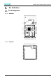

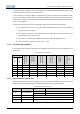
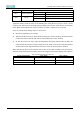
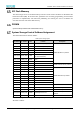
Table Of Contents
- Abstract
- 1. Introduction
- 2. Characteristic
- 3. Pin Definition
- 4. System memory space
- 5. ATE(RF Test Mode)
- 5.1. ATE Command
- 5.1.1. Start MP mode
- 5.1.2. Stop MP mode
- 5.1.3. Set Tx rate
- 5.1.4. Set operational channel
- 5.1.5. Set operational bandwidth
- 5.1.6. Set Tx power
- 5.1.7. Set antenna for Tx
- 5.1.8. Set antenna for Rx
- 5.1.9. Start air Rx mode
- 5.1.10. Start continuous Tx mode
- 5.1.11. Query air Rx statistics
- 5.1.12. Reset air Tx/Rx statistics
- 5.2. Example Command
- 5.1. ATE Command
- 6. Flash Programing
- 7. Electrical parameters
- 8. Antenna Information
- 9. Assembly size and PCB package
- 10. Production Guidelines
- 11. FCC and IC Information
- 11.1. FCC Warning
- 11.2. IC warning
- 11.3. Trace antenna designs
- 11.4. RF exposure considerations
- 11.5. Antennas
- 11.6. Label and compliance information
- 11.7. Information on test modes and additional testing requirements5
- 11.8. Additional testing, Part 15 Subpart B disclaimer
- 11.9. The module is limited to OEM installation ONLY.
- 11.10. The OEM integrator is responsible for ensuring that the end-user has no manual instructions to remove or install module.
- 11.11. The module is limited to installation in mobile or fixed applications
- 12. Package and Label
- Appendix 1: Sales and Technical Support Information

EMC328x Series Wireless Module Data Manual
Copyright of Shanghai MXCHIP Information Technology Co., Ltd.
9
Pin Definition
3.2.1. Definition of General Pin
Table 1 Pin Definition
Pin Number
Name (function
after reset)
Default State
(2)
Function 1
(UART DATA)
Function 2
(LOG UART
RTS/CTS)
Function 3
(SPI)
Function 5
(IR)
Function 7
(I2C)
Function 9
(HS PWM)
Function 10
(LP PWM)
Function 1
4
(USB)
Function 16
(SGPIO)
Function
22
(HS timer trig)
ADC Channel
EMC3280
EMC3285
21,25
35
PA7
(1)
(UART_LOG_TXD)
Internal UP
UART_LOG_TXD
22,24
34
PA8
(UART_LOG_RXD)
Internal UP
UART_LOG_RXD
14
9
PA12
(1)
High-Z
LP_UART_TXD
SPI1_MOSI
HS_PWM0
LP_PWM0
15
8
PA13
(1)
EfusePullCtrl0
LP_UART_RXD
SPI1_MISO
HS_PWM1
LP_PWM1
19
6
PA14
(1)
High-Z
LP_UART_RTS
SPI1_CLK
23
7
PA15
(1)
EfusePullCtrl1
LP_UART_CTS
SPI1_CS
10
11
PA25
EfusePullCtrl2
LP_UART_RXD
HS_USI_SPI_MOSI
IR_TX
LP_I2C_SCL
HS_PWM4
LP_PWM4
HSDM
9
12
PA26
High-Z
LP_UART_TXD
HS_USI_SPI_MISO
IR_RX
LP_I2C_SDA
HS_PWM5
LP_PWM5
HSDP
2,4
37
PA27
(1)
(SWDIO)
Internal UP
LP_UART_RTS
13
10
PA28
EfusePullCtrl3
LP_UART_CTS
HS_USI_SPI_CS
HS_PWM6
LP_PWM0
RREF
12
13
PA30
(1)
External UP
HS_USI_SPI_CLK
HS_PWM7
LP_PWM1
VBUS_OTG
6
5
PB1
EfusePullCtrl4
LP_UART_TXD
SGPIO_OUT
HS_TIM4_TRIG
ADC4
5
4
PB2
High-Z
LP_UART_RXD
SGPIO
HS_TIM5_TRIG
ADC5
1,3
36
PB3
(SWCLK)
High-Z
ADC6
7
31
PB20
High-Z
HS_USI_UART_TXD
HS_USI_I2C_
SCL
HS_PWM12
LP_PWM0
8
30
PB21
High-Z
HS_USI_UART_RXD
HS_USI_I2C_
SDA
HS_PWM13
LP_PWM1
11
3
nRESET
High-Z
nRESET
16
2
VDD
High-Z
VDD
17
1,15
VSS
High-Z
VSS
18,20
Other
NC
High-Z