
Data Sheet
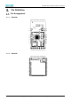

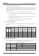
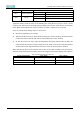
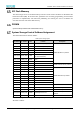
Table Of Contents
- Abstract
- 1. Introduction
- 2. Characteristic
- 3. Pin Definition
- 4. System memory space
- 5. ATE(RF Test Mode)
- 5.1. ATE Command
- 5.1.1. Start MP mode
- 5.1.2. Stop MP mode
- 5.1.3. Set Tx rate
- 5.1.4. Set operational channel
- 5.1.5. Set operational bandwidth
- 5.1.6. Set Tx power
- 5.1.7. Set antenna for Tx
- 5.1.8. Set antenna for Rx
- 5.1.9. Start air Rx mode
- 5.1.10. Start continuous Tx mode
- 5.1.11. Query air Rx statistics
- 5.1.12. Reset air Tx/Rx statistics
- 5.2. Example Command
- 5.1. ATE Command
- 6. Flash Programing
- 7. Electrical parameters
- 8. Antenna Information
- 9. Assembly size and PCB package
- 10. Production Guidelines
- 11. FCC and IC Information
- 11.1. FCC Warning
- 11.2. IC warning
- 11.3. Trace antenna designs
- 11.4. RF exposure considerations
- 11.5. Antennas
- 11.6. Label and compliance information
- 11.7. Information on test modes and additional testing requirements5
- 11.8. Additional testing, Part 15 Subpart B disclaimer
- 11.9. The module is limited to OEM installation ONLY.
- 11.10. The OEM integrator is responsible for ensuring that the end-user has no manual instructions to remove or install module.
- 11.11. The module is limited to installation in mobile or fixed applications
- 12. Package and Label
- Appendix 1: Sales and Technical Support Information

EMC328x Series Wireless Module Data Manual
Copyright of Shanghai MXCHIP Information Technology Co., Ltd.
5
⚫ SPI
▪ Support Motorola SPI serial data transmission
▪ Support master-slave mode
▪ Provide 1 SPI interface
▪ SPI1 (Normal speed): Configurable in master mode with clocks up to 25MHz
▪ Support DMA transmission
▪ Configurable independent interrupt
▪ FIFO Depth: Receive and transmit FIFO queues with 64 words depth, 16 bits per word.
▪ Hardware/software slave device selection function: You can use special hardware to select the
pin from the device chip or use software to control the GPIO mode as the chip select signal of
the SPI slave device.
Programmable features:
▪ Clock frequency: Dynamically control the bit rate of data transmission when set to master mode
▪ The size of each transmitted data (4 to 16 bits)
▪ Clock polarity and phase
▪ When setting to receive serial data in master mode, you can set the delay time of sampling to
achieve higher serial bit rate.
⚫ UART
▪ Supported UART formats: 1 start bit, 7/8 data bits, 0/1 parity bits and 1/2 stop bits
▪ Support hardware flow control
▪ Support for interrupt control
▪ Support IrDA
▪ Support loopback mode for testing
▪ Support TX, RX uses different clocks
▪ Tx channel can use the baud rate generator with fractional number to generate accurate clock
▪ Rx channel supports low power mode
▪ Monitor and eliminate baud rate error and drift on the Rx channel
▪ Support DMA transmission
⚫ IR (Infra Ray)
▪ Support carrier frequency range: 25KHz ~ 500KHz, duty cycle: 1/2 ~ 1/5
▪ Support infrared diode input, support infrared receiver module input
▪ 32*4 bytes Tx FIFO, 32*4 bytes Rx FIFO
⚫ One wire (SGPIO)
▪ Single-wire communication interface for secure encryption chip