
Data Sheet
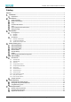
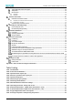
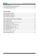
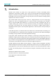
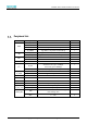
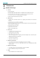
Table Of Contents
- Abstract
- 1. Introduction
- 2. Characteristic
- 3. Pin Definition
- 4. System memory space
- 5. ATE(RF Test Mode)
- 5.1. ATE Command
- 5.1.1. Start MP mode
- 5.1.2. Stop MP mode
- 5.1.3. Set Tx rate
- 5.1.4. Set operational channel
- 5.1.5. Set operational bandwidth
- 5.1.6. Set Tx power
- 5.1.7. Set antenna for Tx
- 5.1.8. Set antenna for Rx
- 5.1.9. Start air Rx mode
- 5.1.10. Start continuous Tx mode
- 5.1.11. Query air Rx statistics
- 5.1.12. Reset air Tx/Rx statistics
- 5.2. Example Command
- 5.1. ATE Command
- 6. Flash Programing
- 7. Electrical parameters
- 8. Antenna Information
- 9. Assembly size and PCB package
- 10. Production Guidelines
- 11. FCC and IC Information
- 11.1. FCC Warning
- 11.2. IC warning
- 11.3. Trace antenna designs
- 11.4. RF exposure considerations
- 11.5. Antennas
- 11.6. Label and compliance information
- 11.7. Information on test modes and additional testing requirements5
- 11.8. Additional testing, Part 15 Subpart B disclaimer
- 11.9. The module is limited to OEM installation ONLY.
- 11.10. The OEM integrator is responsible for ensuring that the end-user has no manual instructions to remove or install module.
- 11.11. The module is limited to installation in mobile or fixed applications
- 12. Package and Label
- Appendix 1: Sales and Technical Support Information

EMC328x Series Wireless Module Data Manual
Copyright of Shanghai MXCHIP Information Technology Co., Ltd.
3
Characteristic
System and storage
⚫ Processor
▪ Dual Core Processor
▪ KM4: Adopt ARM's latest v8M architecture, compatible with Cortex-M4F instruction set
▪ KM4: Adopt ARM's latest v8M architecture, compatible with Cortex-M0 instruction set
▪ Two cores have equal access to SRAM, peripherals and registers
▪ Internal communication between two processors
⚫ KM4 Processor
▪ Compatible with Cortex-M4F instruction set, supporting FPU, DSP, MPU and TrustZone-M
technology
▪ Operating frequency up to 200MHz (configurable)
▪ SWD serial debugging interface, support 8 hardware breakpoints and 4 observation points (SWO
interface function is not supported)
▪ Built-in NVIC interrupt vector table
▪ System timer System tick timer.
▪ 32KB I-Cache and 4KB D-Cache.
⚫ K04 Processor
▪ Compatible with Cortex-M0 instruction set
▪ Operating frequency up to 20MHz
▪ Built-in NVIC interrupt vector table
▪ SWD serial debugging interface, supporting 4 hardware breakpoints and 2 observation points
(SWO interface function is not supported)
▪ System timer System tick timer.
▪ 32KB I-Cache and 4KB D-Cache
⚫ KM4 CPU On-Chip memory
▪ Up to 512KB of continuous space main SRAM with a frequency of 200MHz
▪ (Specific models) can choose up to 4MB PSRAM, frequency up to 50MHz50MHz, 8bit DDR
(specific models)
⚫ KM4 CPU On-Chip memory
▪ Up to 64KB continuous space main SRAM with a frequency of 64MHz
▪ Reserve 1KB SRAM for saving data in low power mode
⚫ GDMA
▪ KM4 and KM0 both contain a GDMA controller.