
Specifications

L506 Hardware Design
Copyright© Shanghai Mobiletek Communication Ltd 40
3.9 Power on/off and reset interface
3.9.1 Pin definition
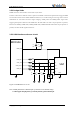
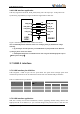
L506 can be powered on by pulling PWRKEY pin down to ground. This pin is already internal pulled
up to 1.8V in module, so external pull-up resistor is not necessary. Placing an ESD protection diode
close to the PWRKEY pin is strongly recommended. Please refer to the following figure for
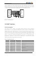
recommended reference circuitL506 also have a RESET pin to reset module. This function is used as
an emergency reset only when AT command “AT+CPOF” has no effect. User can pull RESET pin to
ground, then module will reset. Placing an ESD protection diode close to the RESET pin is strongly
recommended. Please refer to the following figure for recommended reference circuit, you can
pull-down this pin to ground and hold about 150us and then release will force the module enter reset
state.
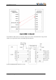
Table 3-15power on/off and reset key define
Pin No.
Net name
I/O Typ.
descriptions
3
PWRKEY
DI
L506 power on/off pin(internal pull-up to
1.8V)
4
RESET
DI
L506 RESET pin(internal pull-up to 1.8V)
Note: Due to the internal partial pressure, the actual measured value of the user is about 0.8v.
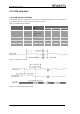
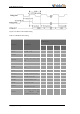
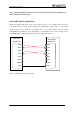
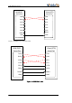
3.9.2 Power on sequence
Table 3-16 power on timing chart.
Ton
Power on low level pulse
115
150
--
ms
Ton(status)
Power on time(According to the
STATUS pin judgment)
2.76
--
25
s
Ton(uart)
Power on time (according the UART
pin judgement)
2.5
--
20
s
VIH
Input high level voltage of
PWRKEY pin
1.17
1.8
2.1
V
VIL
Input low level voltage of PWRKEY
pin
-0.3
0
0.3
V