
Specifications

L506 Hardware Design
Copyright© Shanghai Mobiletek Communication Ltd 29
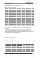
current
IVBAT(power-off)
Power supply
current
in power off
mode
-
-
20
uA
IVBAT(power-save)
Power supply
current
in power save
mode(sleep
mode)
-
-
3
mA
3.4.3 Power Supply Design Guide
Make sure that the input voltage at the VBAT pin will never drop below 3.4V even during a transmit
burst when the current consumption rises up to more than 2A. If the power voltage drops below 3.4V,
the RF performance of module may be affected. Using large tantalum capacitors (above 300uF) will be
the best way to reduce the voltage drops. If the power current cannot support up to 2A, users must
introduce larger capacitor (typical 1000uF) to storage electric power. For the consideration of RF
performance and system stability, some multi-layer ceramic chip (MLCC) capacitors (0.1/1uF) need to
be used for EMC because of their low ESR in high frequencies. Note that capacitors should be put
beside VBAT pins as close as possible. Also User should keep VBAT net wider than 2 mm to
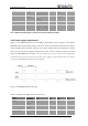
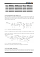
minimize PCB trace impedance on circuit board. The following figure is the recommended circuit.
Figure 3-3 VBAT input application circuit
Note: The Cd, Ce, Cb, Cc and Cf are recommended being mounted for L506, but the Ca, Cb, Ce,
Ccand Cf for tune.
In addition, in order to get a stable power source, it is suggested to use a Zener diode of which reverse
Zener voltage is 5.1V and dissipation power is more than 500mW.
Table 3-8: Recommended Zener diode models