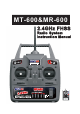
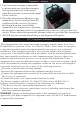
MT-600&MR-600 2.
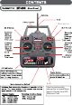
%LQG EXWWRQ 0L[HU Used to electronically change the on-board Mixer options.Choose from OFF, Delta,and V-tail.
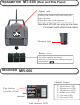
TRANSMITTER MT-600 (Rear and Side Panel) Trainer jack Connects the trainer cord when using the trainer function. (The trainer cord is sold separately. ) Note:Merit MT-600 can only be the slave if connect it with other brand radios. Charging jack Battery cover Use when replacing the battery . Slide the cover downward while pressing the part marked " ".
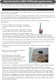
Special note for 2.4GHz FHSS radio system setup Since the 2.4GHz have different characteristics than that of the conventional frequencies, please read this section carefully to enjoy safe flight with the 2.4GHz system. Receiver ’s Antenna installation The MR-600 has two antennas. These antennas have a diversity function to decrease the chance of a receiving error. The wavelength of the 2.
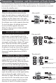
Transmitter antenna 1. The transmitter antenna is adjustable so please make sure that the antenna is never pointed directly at the model when flying as this creates a weak signal for the receiver. 2. Keep the antenna perpendicular to the transmitter's face to create a better RF condition for the receiver. Of course this depends on how you hold the transmitter, but in most cases, adjusting the transmitter antenna so that it is perpendicular to the face will give the best results.
Binding Setup Programming a receiver to recognize the code of only one specitic transmitter. If you change transmitters or add a receiver, you must re-bind before operating your vehicle. 1. Place the transmitter and the receiver close to each other (within one meter). Turn the power switch on the transmitter to the ON position. 2. Press and hold the receiver setup button,then turn the power switch to the ON position. The receiver LED will flash quickly. Release the setup button after 1 second. 3.
Change the transmitter ID The transmitter has a individual randomize ID that is created in the factory, Even it is almost have no chance to meet the same ID transmitter in the same fly field, in case it does happen. T he transmitter has an ID set up function. You can go back to the original factory set ID by h olding the “PDM” when turn on the transmitter, without press the “PDM” bottom, turn it off and on again to get back the original ID.
Transmitter Operation and Movement of Each Servo Before making any adjustments, learn the operation of the transmitter and the movement of each servo. (In the following descriptions, the transmitter is assumed to be in the standby state.) AILERON OPERA TION When the aileron stick is moved to the right, the right aileron is raised and the left aileron is lowered, relative to the direction of flight, and the plane turns to the right.
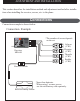
ADJUSTMENT AND INSTALLATION This section describes the installation method and adjustment method after installation when installing the receiver, servos, etc. to the plane. Connections Connection example is shown below. Connection Example *The number of servos depends on the set. Aileron (CH1) Receiver MR-600 Elevator (CH2) Thr ottle (CH3) Rudder (CH4) Receiver switch *Insert four batteries. *When using 5 or more servos, use the nicd battery sold separately.
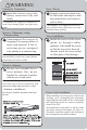
WARNING Connector Connection Insert the receiver, servo, and battery connectors fully and firmly. If vibration, etc. causes a connector to work loose during flight, the plane may crash. Receiver Vibrationpr oofing / Waterpr oofing Vibrationproof the receiver by wrapping it in sponge rubber or some such material. If the receiver may get wet, waterproof it by placing it in a plastic bag. If the receiver is subjected to strong vibration and shock, or gets wet, it may operate erroneously and cause a crash.
Adjustments The operating dir ection, neutral position, and steering angle of each servo ar e adjusted. CAUTION The basic linkage and adjustments of the fuselage conform to the fuselage design drawings and kit instruction manual. Be sure that the center of gravity is at the prescribed position. Adjustment Pr ocedur e Before making any adjustments, set all the SERVO REVERSER switches on the front of the transmitter to the lower (NOR) position. (Switch the switches with a small screwdriver, etc.